Troubleshooting: Rapid Shutdown Not Communicating with Inverter


Does your inverter display show “RSD Comm Loss,” “Rapid Shutdown Communication Error,” or a similar fault code? When this occurs, your entire PV system may come to a halt—output drops to zero, no power is produced, and the root cause isn’t always obvious.
The good news is that this error can almost always be resolved systematically. This guide provides a structured, step-by-step diagnostic approach—starting with the quickest checks and progressing to more targeted isolation. For commercial rooftop and ground-mount systems, this will help you identify the culprit and restore normal operation efficiently.
Understanding the Keep-Alive Signal
Before diving into troubleshooting, it’s essential to understand how a rapid shutdown system stays “awake”—and what happens when it falls silent.
How the Transmitter and Receivers Communicate
A rapid shutdown system consists of two core components: a transmitter and multiple receivers installed at the module level. The transmitter—typically located inside the inverter’s wiring compartment or mounted externally as a standalone device—constantly sends a PLC (Power Line Communication) signal across the DC wiring. This signal, commonly called a “keep-alive” or “heartbeat” signal, tells every RSD receiver in the array to remain closed and allow full module voltage to pass through to the inverter.
For systems that use wireless communication, the keep-alive signal is transmitted via radio instead of over the DC conductors. But the principle is identical: the signal must be present for normal operation.
When an inverter includes an integrated, UL PVRSS-certified RSS Transmitter, the keep-alive signal is generated internally and requires no external transmitter hardware.
What Happens When the Signal Is Lost
The safety mechanism is built around the absence of this signal. Once the transmitter stops broadcasting—whether because AC power to the inverter is interrupted, the transmitter loses its supply voltage, or the transmitter itself fails—the RSD receivers detect the loss. Within a few seconds (typically 10 seconds or less per NEC 690.12 requirements), each receiver automatically disconnects its PV module from the string. The module output voltage drops to a “safety voltage” —typically 0.6V to 0.7V per RSD device, depending on the manufacturer.
When AC power is restored, and the transmitter powers back on, the keep-alive signal resumes and the receivers re-engage, allowing full voltage to flow again. This built-in failsafe ensures that any interruption to the keep-alive signal—regardless of cause—immediately places the system into a safe, de-energized state.
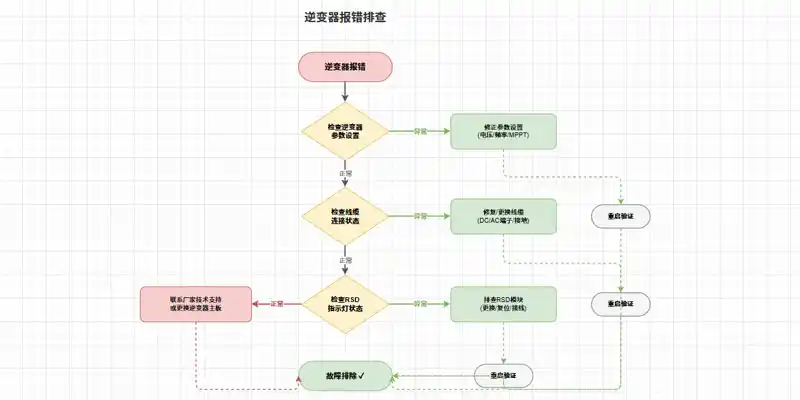
Step 1: Check the Inverter Side
Start your diagnosis at the logical center of the system: the inverter. These are the fastest checks and resolve many cases before any further investigation is needed.
Verify RSD Function is Enabled in Settings
Some inverters allow the rapid shutdown transmitter to be disabled through commissioning software or user settings. Navigate to the inverter’s setup menu and locate the Rapid Shutdown (RSD) or MLRSD section. Confirm that the function is enabled, not turned off. If the integrated transmitter is disabled, the inverter cannot generate the keep-alive signal, and all RSD receivers will remain in shutdown mode.
Measure Power Supply to the Transmitter
The transmitter—whether integrated into the inverter or mounted externally—requires a stable power supply to generate the keep-alive signal. Use a multimeter to measure the voltage at the transmitter’s power input terminals.
For external transmitters, verify that AC power reaching the device is within its specified range. Most commercial transmitters accept either 85–264VAC or 180–550VAC for higher-voltage commercial systems.
For integrated transmitters, measure the voltage at the inverter’s designated RSD output pins. A typical reading should be approximately 12V; if the reading is 0V, the transmitter is not receiving power.
If the power supply is present but the transmitter still shows no activity, the transmitter itself may be faulty.
Step 2: Inspect the Communication Link
If the inverter side checks out, the next step is to examine the path the keep-alive signal travels from the transmitter to the receivers.
For PLC-Based Systems – Check for Interference
In Power Line Communication (PLC) systems, the keep-alive signal rides on the same DC conductors that carry power from the modules to the inverter. This design is elegant but susceptible to several forms of interference.
Cross-talk is a common issue in commercial sites where multiple inverters with integrated transmitters operate in proximity. PLC signals on adjacent DC conductor bundles can interfere with each other, causing receivers to falsely interpret noise as signal loss and enter shutdown mode. The most reliable mitigation is to use a single transmitter for multiple inverters—disabling the built-in transmitters on all but one unit—or to install an external Pure Signal transmitter that coordinates multiple units as a single group.
Improper grounding can also disrupt PLC communication. A single inverter with poor grounding at its HMI board can distort signals across an entire plant. Check continuity between the HMI board grounding screw and a nearby chassis ground point.
If immediately adjacent AC or DC conductors are bundled too closely with the conductors carrying the PLC signal, signal attenuation can occur. Physical separation—a minimum of 8 inches between different transmitter groups—helps maintain signal strength.
For a definitive check, use an RSS Signal Detector (available from manufacturers like Tigo). Place the detector within 2 inches of a TS4-F unit while the system is powered on. If the keep-alive signal is present, the detector LED turns from blue to yellow and emits an audible alert.
For Wired Systems – Test Continuity
If your system uses dedicated control wiring rather than a PLC, inspect the physical communication link directly. Set your multimeter to continuity mode (Ω) and test each conductor end-to-end. Also, inspect every terminal block and connector along the line for:
-
Corrosion (white or green deposits on copper)
-
Loose screws that fail to secure wires
-
Physical damage (cuts, crimps, or crushed insulation)
For systems using RS485 interfaces, be aware that communication can fail when the voltage difference between devices exceeds 100V due to missing communication ground connections. Ensure all communication grounds are properly terminated.
Step 3: Isolate the Faulty Panel-Level Device
If the transmitter and communication link appear operational but the system still reports an RSD communication error, the fault likely resides with one or more individual receivers in the array.
The Divide and Conquer Method
The most efficient technique for locating a single faulty RSD receiver in a multi-module string is the “divide and conquer” approach.
-
Measure safety voltage first. Before any disconnection, power the system on and measure the DC voltage at the inverter’s input terminals. In shutdown mode, each functioning RSD contributes approximately 0.6–0.7V to the total string voltage. Multiply the expected number of modules by 0.6V. If the measured total is lower than the calculation, one or more modules are failing to provide even safety voltage.
-
Split the string in half. With the system fully de-energized and safety protocols observed, disconnect the string at its midpoint. Reconnect one half to the inverter and power on. If that half operates normally and the other half remains in shutdown, the faulty device lies in the non-operational half.
-
Repeat the split within the faulty half until you isolate the specific module-level RSD. This method typically requires no specialized equipment beyond basic hand tools and a multimeter.
Visual Inspection of LED Indicators
Most RSD receivers feature status LEDs that provide immediate diagnostic information without any disconnection. Consult your manufacturer’s manual for exact code meanings, but general indicators include:
-
Solid green or blinking green LED on a receiver → Normal operation, keep-alive signal is being received.
-
Solid red or no LED on an individual receiver → That device is not receiving the signal or has failed internally.
-
All receivers with solid red LEDs → Transmitter issue or widespread signal loss.
For the RSS transmitter itself, normal operation typically shows: Power LED solid (blue) + Signal LED blinking (green. If the Power LED is on but the Signal LED is off, power-cycle the transmitter. If the signal LED remains off after a power cycle, the transmitter may need replacement. A solid red LED on a follower transmitter suggests either incorrect interconnection wiring or a potential malfunction of that specific unit.
Additional diagnostic tools worth considering:
-
An IR camera or surface thermometer can identify non-producing modules—a failed RSD prevents current flow, causing the affected module to appear significantly cooler than neighboring modules under sunlight.
-
If available, a dedicated RSD signal detector can trace the PLC keep-alive signal along the string and pinpoint where the signal drops off.
Step 4: Decide Replace vs. Repair
Once you’ve confirmed a specific RSD receiver is faulty, the next decision is how to address it.
RSD devices are typically sealed, potted electronic modules designed for harsh outdoor environments. Field repair is neither practical nor recommended—opening the housing breaks the environmental seal and invalidates UL certification. Direct replacement is the only viable option.
Before proceeding with replacement:
-
Confirm that the replacement device has identical electrical specifications: input voltage range, maximum continuous current, and system voltage rating.
-
Verify communication protocol compatibility: SunSpec-certified devices generally interoperate, but mixing different manufacturers’ proprietary systems can cause unexpected behavior.
-
If the system uses wireless keep-alive, ensure the new receiver is compatible with your existing transmitter and gateway.
Replacement steps (always follow your manufacturer’s specific instructions):
-
Turn off the AC supply to both the inverter and any external transmitter.
-
Turn off the DC disconnect switch at the inverter.
-
Wait at least 5 minutes for capacitors to discharge.
-
Disconnect the faulty module and remove the RSD device from the racking.
-
Install the replacement device, ensuring all MC4 connectors are fully seated.
-
Reconnect the module to the string.
-
Restore DC connections, then AC power. The transmitter will resume sending the keep-alive signal, and the new receiver should engage normally.
Troubleshooting Summary Table
| Symptom | Possible Causes | Diagnostic Actions |
|---|---|---|
| Inverter displays RSD communication error, zero array output. All modules non-producing. | Transmitter power supply failure; transmitter hardware failure; RSD function disabled in inverter settings. | Verify AC power to transmitter/inverter. Use a multimeter to measure the supply voltage at the transmitter. Check inverter settings to confirm the RSD function is enabled. |
| Only one string reports communication loss; other strings operate normally. | Faulty individual RSD device within that string; loose or corroded PV connector in that string; broken DC conductor. | Measure the safety voltage on the affected string. Use the divide-and-conquer method to isolate the faulty device. Inspect all MC4 connections for corrosion or damage. |
| Intermittent RSD communication errors; the system works, then fails repeatedly. | Electromagnetic interference, loose communication wiring connections; failing transmitter. | Use an RSS signal detector to verify signal presence when failure occurs. Inspect all terminal blocks for intermittent contact. If multiple transmitters are present, consider consolidating to a single transmitter group. |
| LED indicators on RSD receivers show all solid red. | Transmitter not generating keep-alive signal; transmitter powered off. | Check the transmitter Power LED. Verify AC supply to transmitter. Power-cycle transmitter. |
| Power LED on transmitter is on, but Signal LED does not blink. | Internal transmitter failure; incorrect core polarity. | Power-cycle transmitter. For dual-core systems, verify cores are oriented correctly (white side toward the inverter). Replace the transmitter if the signal LED remains off after the correct wiring is confirmed. |
Frequently Asked Questions (FAQ)
Q1: Will the system still produce power if RSD communication is lost?
No. Once the keep-alive signal is lost, all RSD receivers immediately enter rapid shutdown mode. The PV array output drops to near-zero voltage—typically around 0.6V per module. No power will be generated until communication is restored and the transmitter resumes broadcasting the keep-alive signal.
Q2: Can a firmware update cause RSD communication issues?
Yes. Firmware updates to the inverter or to a separate RSS transmitter can introduce changes to the communication protocol. The keep-alive signal parameters may shift, or the encryption/handshaking method may be altered. When performing firmware updates, always verify that the transmitter’s firmware is compatible with the receiver devices on the array. In some cases, a third-party inverter with an integrated RSS transmitter may continue sending a keep-alive signal even when an external CCA is powered off—changing system behavior unexpectedly if firmware updates have altered signal priorities.
Q3: How far can the transmitter be from the furthest panel-level device?
Distance limits vary by communication method and manufacturer specifications. For wired systems (dedicated control wiring), distances of several hundred feet are commonly achievable. For PLC-based systems, signal attenuation increases with cable length, conductor gauge, and the presence of additional loads or connections. For wireless keep-alive signals, range may be shorter, and obstacles such as building structures or metal racks can severely reduce effective range. Exceeding manufacturer-specified distances results in intermittent communication at best and total signal loss at worst. Always refer to your specific transmitter’s installation manual for maximum string length specifications.
Summary & Next Steps
A “RSD Comm Loss” error on your inverter screen is not a catastrophic failure—it is the system doing exactly what it was designed to do: entering a safe state when the keep-alive signal is interrupted. The majority of RSD communication problems originate from one of three sources:
-
The transmitter side — power supply failure, disabled function, or hardware fault
-
The communication link — wiring issues, grounding problems, or PLC cross-talk
-
An individual receiver — failed device or poor connection at the module level
By following a systematic diagnostic order—inverter first, then communication path, then individual devices—you can quickly narrow the possibilities and restore full array output. Always prioritize safety: verify the absence of voltage with a properly rated multimeter before touching any DC conductors, wear appropriate PPE, and never rely solely on system indicators to confirm a de-energized state.
Need to identify an LED error code on your SUNTREE or other RSD device? Our technical support team maintains a comprehensive LED code reference table. Reach out for immediate assistance.
Note: The images in this article are for reference only.