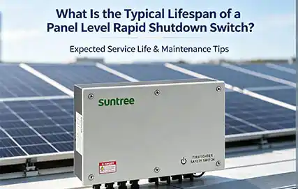
NEC 2026 Panel Level Rapid Shutdown Install Guide | SUNTREE
NEC 2026 maintains and refines the module‑level rapid shutdown requirement: conductors outside the array boundary must drop to 30 V or less within 30 seconds, while inside the boundary, the PV system must limit voltage to 80 V or less within 30 seconds or use a listed PV Hazard Control System (PVHCS) in accordance with Section 690.12(B).
The 2026 revision reorganises Sections 690.12(B) and 690.12(C) to improve clarity — voltage control locations, shock hazard protection methods, and acceptable initiation devices are now laid out in a more usable framework.
Pre-Installation Preparation
Compatibility Check with PV Modules
Confirm that the panel‑level rapid shutdown device (RSD) has:
-
Maximum system voltage ≥ the PV module’s VocVoc (temperature‑corrected per 690.7)
-
Maximum operating current ≥ the module’s IscIsc
Check the datasheets for both the module and the RSD. For typical residential 600 V DC systems, verify string length: Vmax=Voc(STC)×n×temperature_correction_factor — most residential designs use 10–14 modules per string, depending on module VocVoc.
Required Tools and Materials
| Category | Items |
|---|---|
| Test & Measurement | Digital multimeter, DC insulation tester |
| Crimping Tools | MC4‑certified crimping pliers, wire strippers (AWG 10–12), and torque screwdriver |
| Fastening & Management | Stainless‑steel cable ties, dedicated RSD mounting brackets, UV‑rated zip ties, and cable clips |
| Safety PPE | Opaque panel cover sheets, insulated gloves (rated for DC system voltage), safety glasses, hard hat |
| Accessories | MC4 compatible connectors, manufacturer‑specified communication cable, labelling supplies |
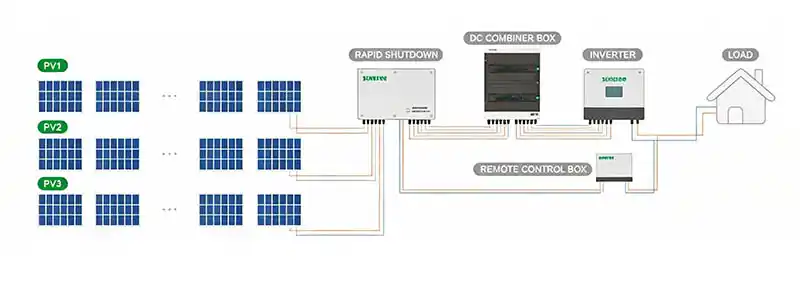
Communication Path Planning
Plan the path between the transmitter (initiator) and each panel‑level RSD. Determine the longest communication distance. For wired systems, ensure total DC circuit length (round‑trip from inverter to the array and back) does not exceed:
-
160 m (525 ft) for single strings
-
120 m (394 ft) for paralleled strings
For powerline‑carrier (PLC) or wireless systems, stay within the manufacturer’s specified range and avoid obstructions that block signal transmission.
NEC 2026 note: The initiation device requirements have been reorganised into clear subdivisions covering type and location, operation, and rules for multiple PV systems — up to six grouped initiation devices can operate together to comply.
1. Mounting the Panel-Level Device
Physical Attachment Method
Secure the RSD device using the manufacturer’s recommended brackets or stainless‑steel cable ties to either:
-
The PV module frame
-
The racking rail adjacent to the module
The device must not be left hanging or suspended only by its cables.
Best practice: Install on the perimeter of the array where possible for easier future servicing.
Clearance requirement: Maintain a minimum 12.7 mm (½ in) between the RSD and any module glass or backsheet. Avoid areas exposed to direct sunlight, rain, snow, or excessive dust.
Grounding and Airflow Considerations
-
Connect the RSD’s equipment grounding terminal to the array grounding system.
-
Ensure that all metal frames and racking are bonded in accordance with 690.43.
-
Keep the RSD clear of the module’s backside ventilation area — do not block cooling airflow.
Important: As of NEC 2026, module‑level power electronics remain the most effective way to ensure the entire array is de‑energised right at the source. The core purpose of rapid shutdown is to protect emergency responders, not to serve as a routine maintenance isolator.
2. DC Wiring Connections
Input Side – Connecting to PV Module
Connect the PV module’s positive and negative output leads to the RSD’s “PV Input” port.
Use only UL‑listed MC4‑compatible connectors certified to match your specific RSD and module brands — mismatched connectors may cause failures and void warranty.
Output Side – Connecting to String Harness
Connect the RSD’s “String Output” port to the main string trunk cable using pre‑assembled MC4 pigtails or compatible connectors.
Critical Safety Reminder: Before making any DC connections, cover the PV modules completely with opaque material or confirm that the combiner box side has been disconnected. The DC conductors stay live whenever sunlight is present.
Installation tips:
-
Cable bending radius > 50 mm to prevent mechanical stress
-
Never short‑circuit output terminals — this may damage the RSD
-
No more than 5 RSDs per string in most MLPE configurations
-
For brand‑specific systems, refer to the UL 3741 application addendum for required device quantities and placement
3. Installing the Transmitter / Initiator
Location Requirements per NEC 2026
The transmitter (initiator) must be installed:
-
Readily accessible — the phrase is now generalised to apply across all initiation methods
-
Plainly visible and accessible to emergency responders
Permissible initiation devices under 690.12(C)(1):
-
Service disconnecting means
-
PV system disconnecting means
-
Listed switches (including E‑stops — the previous plain‑indication marking requirement has been removed for E‑stop type switches)
Exemption note: Systems on non‑enclosed detached structures — such as parking shade structures, carports, and solar trellises — are not required to comply with 690.12. Always confirm applicable exemptions with your local AHJ.
Wiring to Inverter or Controller
Connect the transmitter control cable to the inverter’s Rapid Shutdown port or a dedicated shutdown controller according to the manufacturer’s drawings.
Recommended practices:
-
Use shielded twisted‑pair cable to reduce electromagnetic interference (EMI)
-
Power transmitters from a single breaker (typically 20 A) for synchronised power‑up
-
For systems without an inverter or for charge‑controller setups, use a stand‑alone listed RSD controller package
4. System Testing and Verification
Manual Shutdown Button Test
-
Energise the system under normal operating conditions (daylight, inverter running).
-
Press the transmitter’s Rapid Shutdown button or toggle the listed initiating device.
-
Use a multimeter to measure output voltage at the output side of any panel‑level RSD inside the array boundary — voltage must drop to ≤ 80 V within 30 seconds of initiation.
-
Measure at the array boundary edge — conductors outside the boundary must drop to ≤ 30 V within the same 30‑second window.
AC Power Loss Test
-
With the system operating normally, turn OFF the AC supply at the main breaker or inverter AC disconnect.
-
Observe the transmitter’s status indicators — an automatic shutdown should engage.
-
Confirm voltage reduction at RSD output using the same pass/fail criteria as the manual test.
Always re‑test after any installation modification, inverter replacement, or component change in the rapid shutdown chain.
Documentation and Labeling
NEC 2026 maintains rigorous labelling requirements across all system components. Rapid shutdown signage must remain clearly visible near the initiation switch. Complete documentation for plan review should include:
-
System voltage calculations (690.7)
-
Conductor sizing (690.8)
-
RSD device cut sheets
-
Communication path plan with measured distances
-
UL 3741 listing documentation, if used as the compliance path
Common Installation Errors and Corrections
| Error | Correction |
|---|---|
| Connecting multiple PV modules to a single RSD input | Each RSD serves exactly one PV module. Daisy‑chaining multiple modules into one device violates module‑level shutdown requirements. |
| Tx initiator placed beyond the rated communication distance of the farthest RSD | Measure total communication path length (wire distance or RF range). Add a signal repeater or reposition the transmitter as needed. For wired systems, ensure total DC circuit length does not exceed 160 m for single strings or 120 m for paralleled strings. |
| Using non‑weatherproof connectors or incorrectly crimped MC4 terminals | Use only UL‑certified MC4 connectors from a single manufacturer per connection. Always use the dedicated MC4 crimping tool — a standard electrician’s plier will not create a code‑compliant connection. |
| RSD mounted with no airflow; resting directly against the module backsheet | Maintain ≥ 12.7 mm (½ in) clearance between RSD and module glass or backsheet. Secure with manufacturer‑approved brackets only. |
| Failure to bond the RSD equipment grounding terminal to the array ground | Connect the RSD grounding terminal to the array equipment grounding conductor. In non‑metallic racking, verify that continuity is maintained per 690.43. |
| Exceeding 5 RSDs per string | In systems with per‑string limits, do not exceed 5 RSDs per string. Exceeding this can prevent proper shutdown sequencing. |
Frequently Asked Questions (FAQ)
Q1: Does NEC 2026 require panel‑level or string‑level shutdown?
A: NEC 2026, like its predecessor, requires an effective module‑level shutdown (panel‑level) for rooftop systems on buildings. Inside the array boundary, voltage must be reduced to ≤ 80 V within 30 seconds of initiation — this generally necessitates MLPE (module‑level power electronics) unless a UL 3741‑certified PVHCS is used.
Q2: Can I install rapid shutdown devices on an existing older system?
A: Yes. You must disassemble the existing strings and add an RSD behind each module. Older systems often use different connector brands, so you may need to replace existing connectors with matching MC4‑compatible pairs. Wiring infrastructure typically requires shortening to accommodate each RSD.
Q3: What happens if a single panel‑level RSD fails?
A: That specific PV module will be isolated or will stop outputting power. The remaining RSDs in the same string continue to operate normally. However, the system will require a physical service call to replace the failed RSD. Most MLPE designs fully isolate a faulty unit but cannot bypass it without replacement.
Q4: Are ground‑mount systems exempt from NEC 2026 rapid shutdown requirements?
A: Generally, non‑enclosed detached structures — which can include ground‑mounts securely categorised as “not on or attached to a building” — may be exempt under Exception 2 of 690.12. However, the AHJ has final authority. Always confirm for each project. For building‑attached ground‑mounts (e.g., on a garage wall), rapid shutdown does apply.
Q5: What changed in the 2026 NEC compared to 2023 regarding rapid shutdown?
A: Performance targets (≤ 30 V outside array boundary, ≤ 80 V inside within 30 seconds) remain unchanged. The changes are organisational and clarificatory: initiation device requirements are reorganised into clear subdivisions (type/location/operation/multiple system rules), E‑stop switches are explicitly permitted without “ON/OFF” plain‑indication markings, and the framework is restructured to align with the NEC Style Manual for better usability.
Summary & Next Steps
Correct installation of a panel‑level rapid shutdown system under NEC 2026 hinges on four pillars:
-
Device placement — secure physical mounting with proper clearances (≥ 12.7 mm from module glass) and bonding.
-
Communication integrity — respect maximum cable lengths (≤ 160 m for single strings) and avoid EMI interference.
-
Polarity‑correct DC wiring — each RSD serves one module, using matched MC4 connectors and proper crimping tools.
-
Complete functional testing — both manual switch activation and AC power loss must be verified before system acceptance.
The 2026 code refines — but does not relax — the module‑level shutdown requirement. As more jurisdictions transition to NEC 2026, design to the latest edition while always confirming the specific adopted version with your local AHJ.
CTA: Contact us for SUNTREE’s NEC 2026‑compliant rapid shutdown kit technical data sheets, including compatibility matrices, string length calculators, and UL 3741 pathway documentation.