How to Use a DC Isolator Switch for Safe Solar Inverter Maintenance


For solar maintenance professionals, the DC isolator switch is more than a component—it is a lifeline. Every year, arc flash incidents and electrocution injuries occur because technicians either use the wrong type of switch or operate it in the wrong sequence. Unlike AC mains power, DC arcs do not have a natural zero-crossing point, meaning they can sustain longer and cause catastrophic damage if not properly interrupted.
This article establishes a standard operating procedure (SOP) for using a DC isolator switch for inverter maintenance, covering everything from load break ratings to lockout tagout (LOTO) compliance. By following these steps, field service engineers and safety officers can ensure that maintenance disconnection is not only effective but also survivable.
What Makes a DC Isolator Different
Not every switch is suited for photovoltaic (PV) systems. A standard light switch or general-purpose disconnect lacks the engineering required to handle direct current under load. Here is what sets a true DC isolator apart.
Creating a Visible Air Gap
A fundamental safety requirement for any safe disconnection procedure is verification of isolation. DC isolators are designed to create a physically visible air gap when the handle is moved to the "OFF" position. This means the operator can see through a transparent housing or indicator window that the contacts have physically separated.
This visible break is the cornerstone of lockout tagout (LOTO) compliance. Without a verifiable open circuit, a worker cannot be certain that the downstream cables are de-energized. The air gap ensures that even if the switch’s labeling wears off, the physical evidence of disconnection remains.
Designed for Load Break
A DC isolator is specifically engineered as a load break switch. This means it can safely interrupt current flow while the inverter is operating under full solar irradiance. Inside the enclosure, arc chutes and blow-out magnets stretch and extinguish the DC arc within milliseconds.
Ordinary disconnectors require the circuit to be de-energized before operation. Using a non-load-break device under full PV power will result in sustained arcing, contact welding, and potential housing meltdown. Always verify that your DC isolator is explicitly rated for load break in its datasheet.
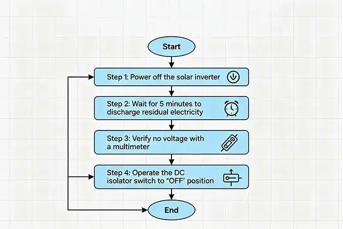
Step-by-Step Safe Disconnection Procedure
The sequence of operations is critical. Reversing the order—disconnecting DC before AC—can expose the technician to backfeed voltage from the inverter’s internal capacitors. Follow these five steps precisely.
Step 1 – Notify All Personnel
Before touching any switch, announce your intent to perform a maintenance disconnection. Inform the control room, building management, and any other workers in the vicinity. Place a temporary warning sign on the inverter’s display panel stating: “MAINTENANCE IN PROGRESS – DO NOT ENERGIZE.” This cognitive lockout prevents accidental remote commands or unauthorized switch closures.
Step 2 – Turn Off the AC Side First
Locate the main AC circuit breaker or disconnect between the inverter and the utility grid. Switch it to the "OFF" position. Why AC first? Modern grid-tied inverters contain large DC link capacitors that store energy. If you disconnect the DC while the AC side remains connected, the inverter may attempt to draw power from the grid, rectify it back to DC, and keep the DC cables energized. By opening the AC side first, you force the inverter to stop switching and allow its capacitors to discharge naturally (typically within 60 seconds).
Step 3 – Operate the DC Isolator to "OFF"
Now move to the DC isolator switch. Grasp the handle firmly and move it from "ON" to "OFF" in a quick, decisive motion. Do not pause or move the handle slowly. Speed is essential because the faster the contacts separate, the less time an arc has to sustain. A slow operation can draw an arc that lasts several hundred milliseconds, leading to contact pitting, degraded switch life, and potential injury.
Step 4 – Verify Zero Voltage
Never trust a switch alone. After operating the isolator, retrieve a calibrated multimeter rated for CAT III 1000V DC. Measure between DC+ and DC- on the load side (inverter-facing terminals) of the isolator. Then measure between each terminal and ground. Confirm that the voltage reads below 5V DC.
Safety warning: PV strings can induce voltages from ambient light even when disconnected. A properly functioning isolator will block this, but always verify.
Step 5 – Apply Lock and Tag
With zero voltage confirmed, apply your personal safety lock through the isolator’s hasp or lockable handle. Ensure the lock is unique to you. Attach a durable tag listing:
-
Your name and contact number
-
Date and time of lock application
-
Nature of maintenance work
This lockout tagout step transforms the DC isolator from an electrical device into a legal and procedural barrier against re-energization.
Common Operational Mistakes
Even experienced technicians make errors. Recognizing these high-risk behaviors is the first step toward eliminating them.
Mistake 1: Operating the switch slowly under full load. As noted above, hesitation prolongs arcing. The result is carbonized contacts, loss of rated interrupting capacity, and potential arc flash to the operator’s hand. Always practice a swift, committed movement.
Mistake 2: Using a non-load-break switch as a DC isolator. Some installers mistakenly use photovoltaic DC circuit breakers as routine disconnects. However, breakers are not optimized for frequent manual load breaking. Over time, their trip mechanisms degrade. A dedicated load break switch is designed for thousands of maintenance operations.
Mistake 3: Failing to verify voltage after disconnection. Stored charge in inverter capacitors or induced voltage from long cable runs parallel to AC lines can present 50–100V DC even when the isolator is open. Without verification, a technician might assume zero energy and touch live terminals. Always measure—never assume.
How to Select the Right DC Isolator for Maintenance
Choosing the correct component is as important as operating it correctly. When specifying a DC isolator for inverter maintenance disconnection, evaluate these four criteria.
Visible ON/OFF indication and lockable handle. The switch must have a clear, unambiguous handle position. Red/green indicators are preferred. An integral lockout hasp—or at least a provision for a padlock—is mandatory for LOTO compliance.
Ingress protection (IP) rating. For outdoor PV installations (rooftop or ground-mount), select at least IP65. This ensures the switch remains dust-tight and protected against low-pressure water jets. Rain, condensation, or dust ingress can cause tracking and flashover inside the enclosure.
DC voltage and current rating. The DC switch rating must equal or exceed the maximum system voltage and the short-circuit current (Isc) of the PV string. Oversizing is acceptable; undersizing is dangerous. Note that DC voltage breaks down differently than AC—a 600V AC switch may fail catastrophically at 300V DC.
Auxiliary contacts (optional but recommended). For advanced safety, choose a DC isolator with built-in auxiliary contacts. These signal the inverter’s control board when the isolator is opened. The inverter can then:
-
Shut down arc-fault detection circuits
-
Log the disconnection event
-
Prevent automatic re-closure until a manual reset
Re-energizing After Maintenance
Restoring power follows the reverse order of disconnection. Never shortcut the process.
-
Remove the lock and tag. Only the person who applied the lock may remove it. Verify that all tools, test leads, and debris are cleared from the inverter compartment.
-
Confirm all personnel are clear. Verbally announce: “Energizing in 30 seconds.” Check the area to ensure no one is touching cables or terminals.
-
Close the DC isolator first. Move the handle decisively from "OFF" to "ON". Listen for a clean switching sound—no buzzing or arcing.
-
Close the AC circuit breaker. Restore grid connection and monitor the inverter display for normal startup (grid synchronization, MPPT tracking).
-
Check operational status. Verify that the inverter produces expected power and that no fault codes (e.g., “Isolation Fault” or “Arc Fault”) appear.
Frequently Asked Questions (FAQ)
Q1: Can a DC isolator switch be used as a regular circuit breaker?
A: No. A DC isolator provides no overcurrent protection. It cannot trip on overload or short circuit. You must install a DC-rated circuit breaker or fuses in series upstream of the isolator for fault protection. The isolator is for manual disconnect only.
Q2: How often should a DC isolator switch be replaced?
A: With normal maintenance operations, a quality load break switch can last over 10 years. However, inspect annually for contact wear by measuring voltage drop across closed contacts. Replace immediately if the handle feels loose, the enclosure shows carbon tracks, or operation becomes noisy.
Q3: What is the difference between a 2-pole and 4-pole DC isolator?
A: A 2-pole isolator switches both the positive and negative conductors of a single PV string. This is sufficient for floating (ungrounded) systems. A 4-pole isolator can switch two independent strings or one string plus two auxiliary signal lines. Use a 4-pole when you need interlocking with monitoring systems or when combining multiple strings in parallel.
Summary & Next Steps
Safe maintenance disconnection using a DC isolator is not optional—it is the difference between a routine service call and a fatal accident. The golden rule to remember is: AC first, DC second, lock and tag, then verify. Never trust a switch alone; always measure zero voltage with a meter.
For safety officers, the next step is implementing a formal LOTO procedure that includes DC isolators in your PV system documentation. For field technicians, the habit to build is speed: quick operation of the isolator handle, followed by methodical voltage verification.
Contact SUNTREE to download PV System LOTO Safety Card – a pocket-sized, waterproof reference card covering the five-step disconnection sequence, voltage verification points, and emergency response contact numbers. Equip every member of your maintenance team with this life-saving tool.
Note: The images in this article are for reference only.