How to Select DC MCCB Breaking Capacity for PV Systems | SUNTREE
Breaking capacity is the most critical safety parameter for DC Molded Case Circuit Breakers (MCCBs) in solar applications. Selecting the wrong rating can lead to catastrophic failure—including fire or equipment explosion. This guide explains how to accurately calculate fault currents and match them to the correct DC MCCB breaking capacity for every position in your PV system.
What is Breaking Capacity and Why It Matters
In photovoltaic systems, a DC MCCB serves two primary functions: carrying the normal operating current and interrupting dangerous fault currents. Breaking capacity defines the maximum current a circuit breaker can safely interrupt at its rated voltage. If a fault exceeds this limit, the breaker cannot guarantee safe operation.
The Difference Between Service and Ultimate Breaking Capacity
Two critical ratings define a DC MCCB’s breaking performance:
-
Ultimate Breaking Capacity (Icu): This is the maximum fault current the breaker can interrupt once. After interrupting at the Icu, the breaker is likely damaged and must be replaced. It successfully cleared the fault, but its internal contacts and arc chute may be compromised.
-
Service Breaking Capacity (Ics): This rating indicates the fault current the breaker can interrupt multiple times while remaining functional. Typically expressed as a percentage of Icu, Ics is the more important rating for photovoltaic systems.
For PV systems, always prioritize Ics over Icu. Solar installations require high reliability—a single fault should not take down protective devices across the array. In battery-coupled systems, especially, fault events can occur repeatedly. Specifying a DC MCCB with 100% Ics ensures the device remains operational after clearing a fault.
The Risk of Insufficient Breaking Capacity
Installing a DC MCCB with inadequate breaking capacity creates serious hazards:
-
Contact welding: The electromagnetic forces generated by a high-current arc can fuse the breaker’s contacts. The mechanism cannot open the circuit, and the fault continues.
-
Arc flash ejection: When internal arc extinguishing fails, superheated plasma and molten metal can explode out of the breaker enclosure, endangering nearby personnel and equipment.
-
Fire ignition: Sustained arcing generates extreme temperatures that can ignite insulation, wiring, and adjacent combustible materials.
A real-world example: a 1500V DC string combiner box with a 10kA-rated MCCB experienced a battery-side backfeed fault of 18kA. The breaker could not interrupt the current—contacts welded shut, and the resulting fire destroyed four string combiners.
Estimate the Worst-Case Short-Circuit Current
Before selecting a DC MCCB, you must calculate the maximum available fault current at each point in the system. Undersizing the breaking capacity is the most common—and most dangerous—selection error.
Sources of Fault Current in PV Systems
Unlike AC systems, where the grid is the primary fault source, photovoltaic systems have two potential short-circuit current sources:
-
PV array side: The array itself generates fault current. However, because PV modules are current-limited devices, the maximum fault current from a string or array is limited to approximately 1.2 to 1.5 times the short-circuit current (Isc) of the array. For a typical string with 10A Isc modules, the maximum array fault current might be 15A—very low.
-
Grid or battery side: This is where dangerous fault currents originate. Grid-connected inverters can backfeed from the AC side. But the most significant hazard comes from battery energy storage systems (BESS). Lithium-ion battery banks can deliver enormous short-circuit currents—often 20 to 30 times their rated current. A 200Ah, 48V battery rack can produce over 6,000A of fault current. At utility-scale voltages, battery fault currents easily exceed 50kA.
Where to Find Information
To estimate fault current, consult these sources:
| Component | Look For | Notes |
|---|---|---|
| Inverter datasheet | “Maximum output short-circuit current” or “Backfeed fault current.t” | Represent the worst-case current from the AC grid or battery through the inverter |
| Battery datasheet | “Maximum short-circuit current” or “Peak discharge current.” | Often calculated from internal resistance: I = Vnom / |
| PV module datasheet | Isc | Multiply by 1.5 for the array fault contribution |
For battery systems without a published short-circuit current rating, calculate it using:
I_sc = V_oc / (R_battery)
Where R_battery = (V_oc / I_peak). If unknown, assume a conservative 10x to 20x multiple of the rated continuous current for lithium-ion chemistries.
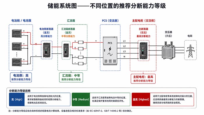
Match Breaking Capacity to the Location
A common mistake is using the same breaking capacity rating for every DC MCCB in a system. Different locations experience vastly different potential fault currents. Match the breaker to the risk.
At the Combiner Box – Array Side
Recommended breaking capacity: 10kA to 15kA DC
Combiner boxes aggregate strings before the inverter. The only fault current available here comes from the PV array itself—limited to roughly 1.5× Isc. Even for large arrays, the fault current rarely exceeds 2kA to 5kA. A 10kA DC MCCB provides ample margin.
However, there is one exception: if the combiner box is also connected to battery storage downstream through a bi-directional inverter, a fault in the combiner could be fed from the battery side. In that case, use the battery-side rating.
At the Battery Rack – Energy Storage Side
Recommended breaking capacity: 25kA to 50kA DC
Battery racks are the most dangerous fault current sources in any photovoltaic system. A lithium-ion battery string’s internal resistance is extremely low, allowing massive short-circuit currents until the internal fuse or contactor opens.
Example values by system scale:
| System Scale | Voltage | Typical Battery Fault Current | Recommended MCCB Icu (DC) |
|---|---|---|---|
| Residential | 48V–400V | 3kA–10kA | 15kA–25kA |
| Commercial | 600V–800V | 10kA–30kA | 25kA–50kA |
| Utility-scale | 800V–1500V | 30kA–100kA+ | 50kA–100kA+ |
When in doubt, measure or calculate conservatively. A battery rack rated for 500A continuous current with an internal resistance of 5mΩ produces I_sc = 800 / 0.005 = 160,000A for milliseconds before protection operates. Your DC MCCB must survive this.
At the Main DC Panel – Grid/Battery Combined
Recommended breaking capacity: Highest in the system
The main DC distribution panel experiences the sum of available fault currents from all sources. If both the PV array and battery can contribute simultaneously—or if grid backfeed is possible—the available fault current can be extreme.
Select a main DC MCCB with a breaking capacity equal to or exceeding the highest single source. Redundancy matters here: oversizing by 20% to 30% is common practice.
Consider Selective Coordination
Breaking capacity selection does not happen in isolation. For multi-level photovoltaic systems, selective coordination ensures the right breaker trips at the right time.
What is Selective Coordination
Selective coordination means that when a fault occurs downstream, only the breaker immediately upstream of the fault opens. All upstream breakers remain closed, preserving power to healthy circuits.
Example: A short circuit in a single string should trip only the string’s DC MCCB. The combiner box breaker and main panel breaker should stay closed, allowing the rest of the array and storage system to continue operating.
How Breaking Capacity Affects Coordination
Achieving selective coordination requires matching both trip curves and breaking capacities across device tiers:
-
Downstream breakers: Lower Icu rating, faster trip curve.
-
Upstream breakers: Higher Icu rating, slower trip curve with intentional delay.
If a downstream breaker has inadequate breaking capacity for the available fault current at its location, selective coordination fails—the upstream breaker may trip instead, or both may trip simultaneously.
Rule of thumb: For every tier moving toward the source, increase ICU by approximately one step. This ensures the upstream device can “wait” while the downstream device clears the fault.
Common Selection Errors
Even experienced engineers make these mistakes. Avoid them:
Error 1: Using the same breaking capacity throughout the system
A designer assumes 15kA is sufficient everywhere because the battery datasheet lists “15kA peak.” However, fault current at the battery terminals can exceed that during certain failure modes. Always add margin.
Error 2: Specifying Icu while ignoring Ics
An MCCB with Icu = 25kA but Ics = 50% may survive only one fault near its limit. After clearing that fault, it must be replaced. For systems where fault events are possible during commissioning or maintenance, specify Ics ≥ 75% of Icu, and preferably 100%.
Error 3: Forgetting to reassess after system expansion
Adding a second battery rack doubles the available fault current. Adding a larger inverter increases grid backfeed capability. Always re-calculate worst-case fault current when modifying an existing photovoltaic system—and upgrade DC MCCBs accordingly.
Frequently Asked Questions
Q1: Can I use a DC MCCB with a breaking capacity higher than needed?
Yes. Using a higher-rated MCCB does not create any safety or operational problem. The breaker will still trip at its designed current threshold. The only downsides are higher cost and potentially larger physical size. For critical locations like battery racks, oversizing is a best practice.
Q2: What is the typical breaking capacity for a residential solar system?
For a grid-tied residential PV system without battery backup: 6kA to 10kA DC is typically sufficient for the DC combiner panel. For a residential system with lithium battery storage, increase the battery-side DC MCCB to 15kA to 25kA. At the main DC panel where battery and array combine, use 25kA minimum.
Q3: Does breaking capacity degrade over time?
Yes. Each interruption of a fault current erodes the contacts and arc chute slightly—especially near the Icu rating. After multiple fault interruptions, the effective breaking capacity decreases. This is why specifying a higher Icu than calculated and requiring high Ics is important for long-term reliability. For systems likely to experience repeated faults, consider using DC MCCBs with replaceable contact assemblies.
Summary & Next Steps
Selecting the correct breaking capacity for DC MCCBs in photovoltaic systems comes down to three steps:
-
Estimate worst-case short-circuit current at each location—distinguish between array-limited and battery/grid-limited sources.
-
Match breaking capacity to the location—low for combiner boxes, high for battery racks, and highest for main DC panels.
-
Design for selective coordination—increase ICU tier by tier moving toward the source, and always prioritize ICS over ICU alone.
The bottom line: When in doubt, go higher. A DC MCCB with excess breaking capacity margin costs slightly more but provides safety and peace of mind. An undersized breaker puts your entire photovoltaic system—and the people working near it—at risk.
Need help selecting the right DC MCCB for your photovoltaic system? [Contact SUNTREE] for application engineering support, product datasheets, and project-specific recommendations.
Note: The images in this article are for reference only.