 English
 Bahasa Melayu
 Suomen kieli
 عربي
عربي  Português
 Français
 Pусский
 Español
How to Fix Voltage Drop Across DC Circuit Breaker in Long Solar Strings


In commercial solar PV systems, excessive voltage drop across a DC circuit breaker is more than just an efficiency problem—it directly reduces energy yield and signals underlying contact issues that can escalate into safety hazards. When a string runs hundreds of meters from the array to the combiner box or inverter, even a few tens of millivolts across the breaker can compound with cable losses, pushing string voltage below the inverter’s MPPT tracking window. This guide explains how to diagnose, fix, and prevent excessive voltage drop across DC breakers in long solar strings, with practical steps for O&M engineers and system owners.
Understanding Normal vs. Excessive Voltage Drop
What is Acceptable
A healthy DC circuit breaker operating at full rated current should exhibit only a small voltage drop across each pole—typically in the range of 20 to 50 millivolts. This corresponds to a contact resistance on the order of 0.2 to 0.5 mΩ for a typical current level. If the measured voltage drop exceeds 100 mV under normal operating conditions, further investigation is warranted. For higher-current circuits, the acceptable limit is slightly higher, but any reading above 200 mV under full load should be treated as abnormal and addressed promptly.
From a system-wide perspective, industry standards recommend limiting total DC voltage drop across all circuit components—cables, connectors, and breakers—to below 2% for source circuits and 1–3% for output circuits under IEC 62548 guidelines. However, the drop contributed specifically by the breaker should be a small fraction of that total. Tracking voltage drop trends over time is also critical: a sudden jump in millivolt readings suggests contact wear or loose terminations, while a gradual increase indicates progressive oxidation or thermal degradation of contacts.
How to Measure Correctly
Accurate measurement requires the system to be operating at its typical load current—ideally near maximum power point conditions.
Step-by-step measurement procedure:
-
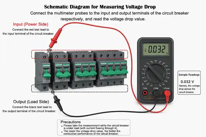
Set up your meter. Use a high-precision digital multimeter with millivolt resolution. Set it to the lowest possible DC voltage range that still exceeds the expected reading.
-
Access the breaker safely. Open the combiner box or DC distribution panel. Identify the breaker in question and confirm it is in the closed position.
-
Measure voltage drop. Place the positive probe on the input terminal of the breaker and the negative probe on the output terminal of the same polarity—positive to positive, or negative to negative. The meter displays the voltage differential directly across the breaker. Do not measure from positive input to negative output; that yields the full string voltage, not the drop across the breaker.
-
Record the value. Note the reading under steady operating conditions. Compare it against the breaker’s datasheet specifications for typical contact resistance.
-
Compare across breakers. If multiple strings share a combiner box, measure the voltage drop across each breaker for the same string current. A breaker reading significantly higher than its neighbors is a strong indicator of a localized problem.
Loose or Corroded Terminals
Loose or corroded terminals are the most common cause of excessive voltage drop across DC circuit breakers in photovoltaic systems. Connection problems manifest as localized high resistance, converting electrical energy into waste heat and producing measurable voltage drop.
Diagnosis
Primary detection method: Use a thermal imaging camera to scan the breaker terminals under load. A temperature differential of 10°C or more between the terminal and the surrounding breaker casing or adjacent terminals is a clear signal of a poor connection. For commercial plants, thermal imaging can be performed with handheld cameras during routine walkdowns or with drone-based systems for large-scale ground-mount arrays.
Visual inspection: Inspect terminals for discoloration, white or green powder-like deposits, darkened insulation on adjacent wires, or any signs of melting or charring around the connection point.
Symptom checks: A loose terminal will cause a voltage drop that is proportional to current—the drop increases as string current rises toward peak generation hours. Intermittent voltage fluctuations in monitoring data often point to vibration-loosened connections.
Solution: Clean and Re-torque
Step 1: Isolate and lock out. De-energize the string by opening the upstream disconnect or turning off the inverter and waiting for the manufacturer-specified discharge time. Verify the absence of voltage with a rated meter before proceeding.
Step 2: Disconnect and clean. Remove the conductor from the terminal. Clean corrosion using a fiberglass brush or non-woven micro-abrasive pad for light oxidation; for heavy corrosion or pitting, replace the terminal lug entirely. Use 99% isopropyl alcohol and lint-free swabs to remove oils, dust, and debris. For aluminum conductors, apply an antioxidant compound rated for electrical terminations to prevent future oxidation.
Step 3: Inspect the conductor. Cut back any conductor showing signs of heat damage. Strip fresh copper and re-terminate.
Step 4: Re-torque to specification. Tighten the terminal screw to the manufacturer’s specified torque value using a calibrated torque screwdriver or torque wrench. Terminal tightness cannot be reliably judged by feel alone; under-torquing leaves excessive resistance, while over-torquing can strip threads or crack the breaker housing.
Step 5: Verify. Re-energize the string and remeasure the voltage drop. A properly re-torqued terminal should return the reading to the normal range.
Worn or Pitted Contacts Inside the Breaker
DC circuit breakers are subject to more severe contact wear than their AC counterparts because direct current has no natural zero-crossing point to extinguish arcs. When a DC breaker opens under load, the sustained arc erodes the contact surfaces, creating pits and uneven surfaces that increase contact resistance even when the breaker is closed.
Why Contacts Deteriorate
Each time the breaker interrupts load current, an electric arc forms across the separating contacts. DC arcs do not self-extinguish; they persist until the arc is mechanically stretched and cooled within the arc chute. This process transfers contact material from one surface to the other, gradually producing a worn, pitted, or oxidized contact interface. The resulting increase in contact resistance is directly measurable as a higher voltage drop across the closed breaker.
Even repeated manual toggling of the breaker under live circuit conditions—a common but inadvisable practice—accelerates contact wear. Each switching operation adds incremental damage.
Solution: Replace the Breaker
Internal contacts cannot be field-repaired or reconditioned. Once pitting or wear has occurred, the only effective remedy is replacement.
Replacement procedure:
-
Select a replacement breaker of identical or upgraded specifications.
-
De-energize the string and verify zero voltage.
-
Remove the defective breaker, noting wire termination positions.
-
Install the new breaker, applying anti-oxidation compound to terminals.
-
Torque all terminals to specification.
-
Re-energize and measure voltage drop. A new, healthy breaker should read under 50 mV at rated current.
Important: Always use DC-rated circuit breakers in solar PV strings. AC breakers lack sufficient arc-chute depth and magnetic blowout strength for DC interruption and can fail catastrophically.
Undersized Breaker for the Application
A circuit breaker that is correctly sized for normal operation may nevertheless experience accelerated contact degradation if it runs continuously near its rated current. This condition is especially common in long strings where module technology upgrades have increased output current without corresponding breaker upgrades.
The Overheating Effect
Circuit breakers contain bimetallic trip elements that respond to heating from current flow. When operated continuously at or near rated current, the internal temperature of the breaker rises above design expectations. Elevated temperatures accelerate oxidation of contact surfaces and can relax spring pressure, both of which increase contact resistance over time. Higher contact resistance produces more I²R heating, creating a self-reinforcing cycle that progressively degrades performance.
Solution: Upgrade to a Higher Rated Breaker
Calculate the required rating. NEC 690.9(B) requires overcurrent protection devices for solar PV circuits to be sized at 125% of the maximum circuit current for continuous duty. The correct formula is:
Breaker minimum rating = Istring (max power current) × 1.25
For example, a string with IMPP = 32 A requires a DC breaker rated at least 40 A (32 × 1.25 = 40). If multiple strings are combined, sum the currents before applying the multiplier.
Select a larger rating. Choose the next available standard size above the calculated minimum. If the calculation yields 40 A, a 50 A, or a 63 A DC breaker provides ample safety margin and reduces operating temperature, extending contact life. The higher rating does not reduce protection—the breaker still trips on fault currents—but runs cooler at normal load.
Verify voltage rating. The breaker’s rated voltage must exceed the system’s maximum possible voltage, including low-temperature open-circuit voltage rise. For 1000 VDC systems, use breakers rated at 1000 V or higher. For 1500 VDC commercial systems, select components explicitly rated for 1500 VDC.
Step-by-Step Fix Procedure
Step 1 – Document the fault. Record the voltage drop measurement, operating current, string voltage, ambient temperature, and any history of nuisance tripping or abnormal breaker behavior.
Step 2 – De-energize and LOTO. Shut down the inverter, open the string disconnect, and verify zero voltage. Apply lockout/tagout.
Step 3 – Perform terminal inspection and remediation. Inspect all terminals for discoloration, corrosion, or heat damage. Clean and re-torque all connections to specification. Do not skip this step even if the terminals appear clean—loose connections are the most common root cause.
Step 4 – Re-test. Restore power and remeasure voltage drop. If the reading returns to normal, the issue was terminal-related. If the reading remains elevated, proceed.
Step 5 – Perform breaker substitution test. Replace the suspect breaker with a new DC breaker of the same rating. Re-energize and measure. If the voltage drop normalizes, the original breaker had internal contact damage.
Step 6 – If the problem persists after breaker replacement, inspect the conductors leading to the breaker for damage, inspect the busbars in the combiner box for signs of overheating, and check for voltage drops across upstream and downstream connections.
Preventive Measures
Proper Terminal Torquing
Use a calibrated torque screwdriver or torque wrench on every terminal during new installations. Terminal torque specifications are listed in breaker datasheets and combiner box manuals. Document torque values applied for quality assurance and future maintenance reference.
Thermal Imaging Inspections
Perform thermal scans of all DC distribution equipment at least every 12 months. Commercial plants with high utilization factors or located in high-ambient-temperature environments should consider semi-annual inspections. Thermal cameras with a sensitivity of NETD ≤ 0.1 K are sufficient for breaker terminal inspections, though higher-resolution units provide better diagnostic detail.
Breaker Oversizing Strategy
For frequently operated breakers—such as those in combiner boxes that are opened for string troubleshooting or seasonal maintenance—or for systems with known future expansion plans, consider using a breaker rating one size larger than the NEC minimum. The cooler operating temperature significantly extends contact life.
Keep a Maintenance Log
Track voltage drop measurements across each breaker during scheduled maintenance. A rising trend over time—even before crossing a pass/fail threshold—signals progressive contact degradation and allows proactive replacement before the problem affects production.
Frequently Asked Questions (FAQ)
Q1: How much voltage drop is considered too high for a DC breaker?
A: Under full load, any reading consistently above 100 mV warrants investigation. Readings exceeding 200 mV (0.2 V) are definitely abnormal and require action. For large commercial systems with breakers rated above 100 A, the acceptable limit is proportionally higher, but any reading that exceeds the manufacturer's datasheet specifications should be addressed. The most important diagnostic indicator, however, is change over time—a breaker that reads 50 mV today and 120 mV in six months has a developing problem.
Q2: Can voltage drop across a breaker cause the system to shut down?
A: Generally, voltage drop from a single breaker will not directly cause a shutdown. However, in long strings where the cumulative voltage drop from cables, connectors, and breakers pushes the total operating voltage below the inverter’s MPPT window, the system may lose tracking capability. In extreme cases, if the breaker runs hot enough to cause thermal tripping of its bimetallic element, the breaker will open and shut down the string. More commonly, the breaker simply wastes energy as heat without tripping.
Q3: Is the voltage drop the same for AC and DC breakers?
A: The measurement principle is the same: voltage drop = current × contact resistance. However, DC breakers experience contact degradation more rapidly than AC breakers because DC arcs lack zero-crossing points to naturally extinguish. For this reason, voltage drop problems are more common and more severe in DC circuits. Always use DC-rated breakers in PV applications; AC breakers installed on DC circuits will fail prematurely and pose significant fire hazards.
Q4: How often should I measure voltage drop across DC breakers in a commercial system?
A: At a minimum, measure during each annual preventive maintenance shutdown. For large plants with >1 MW capacity or systems with high utilization factors, consider semi-annual measurements. Any breaker that experiences a fault interruption event should be tested immediately afterward, as arc damage from fault clearing accelerates contact wear dramatically.
Summary & Next Steps
Excessive voltage drop across a DC circuit breaker in a long solar string is almost always caused by one of three factors: loose or corroded terminals, worn internal contacts, or an undersized breaker running too hot. Terminal issues can be fixed through cleaning and proper re-torquing; worn contacts require breaker replacement; and undersized applications call for upsizing to an appropriately higher rating using the NEC 125% rule.
The diagnostic workflow is straightforward: measure, inspect thermally, isolate the root cause, and apply the correct remediation. For commercial system owners and O&M teams, the most cost-effective strategy is preventive—regular thermal imaging and voltage drop logging catch developing problems before they impact production.
Note: The images in this article are for reference only.