 English
 Bahasa Melayu
 Suomen kieli
 عربي
عربي  Português
 Français
 Pусский
 Español
Can a DC MCB Handle Both Overload and Short Circuit Protection? | SUNTREE


Yes. A DC miniature circuit breaker (MCB) is designed to handle both overload and short‑circuit faults. In fact, this dual‑function capability is one of the main differences between an MCB and a fuse. While a fuse offers only one‑time protection and must be replaced after operation, an MCB combines two distinct internal trip mechanisms—thermal and magnetic—to respond appropriately to different types of overcurrent events. This article explains how these two mechanisms work together, what they can protect against, and what they cannot.
The Two Types of Faults a PV System Faces
Before diving into the mechanisms, it is helpful to understand the two fault categories that can occur in a solar photovoltaic system. They differ not only in magnitude but also in how quickly they must be cleared.
Overload – A Slow and Steady Rise
An overload happens when the current exceeds the rated value but stays well below the short‑circuit level. Common causes include connecting an extra string of PV modules beyond the design limit, a malfunctioning inverter that draws excessive current, or a gradual degradation of insulation that increases leakage. Overload currents are typically only a few times the rated current—for example, 1.5× to 3× In—and they can persist for seconds or even minutes. Although not immediately destructive, sustained overload generates excessive heat, accelerating ageing of cables and terminals, and may eventually lead to insulation failure or fire.
Short Circuit – A Sudden Surge
A short circuit occurs when the positive and negative conductors come into direct contact, or when an internal fault creates a very low‑impedance path. In PV systems, this can happen due to damaged cables, loose connections, or inverter internal failures. The current then rises abruptly to extremely high values—often 10 to 20 times the rated current—within a fraction of a millisecond. Such a surge produces enormous electromagnetic forces and rapid temperature rise. If not interrupted within milliseconds, it can melt conductors, destroy equipment, and cause arc flashes that pose serious safety risks.
Because the two fault types require completely different response times—slow for overload, near‑instantaneous for short circuit—a single protection device must incorporate two independent sensing mechanisms. That is exactly what a DC MCB does.
Mechanism One – The Thermal Trip for Overloads
The thermal trip element is responsible for detecting and clearing overload conditions. Its operation relies on a simple but reliable electromechanical component: the bimetallic strip.
How a Bimetallic Strip Works
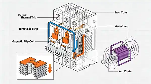
A bimetallic strip consists of two layers of metals with different coefficients of thermal expansion, bonded firmly together. Common combinations include brass and steel, or copper and steel. When current flows through the strip, it heats up due to the inherent resistance. Because the two metals expand at different rates, the strip bends toward the side with the lower expansion coefficient. This bending motion is transferred to a latch mechanism. When the deflection is sufficient, the latch releases and the contacts open under spring force, interrupting the circuit.
The heat generated is proportional to I² × t, so the amount of bending depends on both the magnitude and duration of the overcurrent. This gives the thermal trip its characteristic “inverse‑time” behaviour—the higher the overload, the faster the strip bends and the quicker the MCB trips.
Why It's Delayed by Design
The thermal trip is intentionally designed with a certain time delay. For small overloads, the delay may be several minutes; for heavier overloads, it may be a few seconds. This deliberate lag serves two important purposes:
-
Avoid nuisance tripping – Many loads, including some DC‑DC converters and inverters, draw momentary inrush currents during startup that are higher than the rated current but last only a few cycles. A delayed response allows these normal transients to pass without interruption.
-
Coordination with upstream devices – In a cascaded protection scheme, the thermal delay helps ensure that only the nearest MCB to the fault trips, leaving upstream breakers unaffected.
However, the thermal trip is too slow for a severe short circuit. That is why a second, faster mechanism is essential.
Mechanism Two – The Magnetic Trip for Short Circuits
For extreme overcurrents, the MCB relies on a magnetic trip, also called an electromagnetic trip. This element acts almost instantaneously, without any intentional delay.
The Electromagnetic Coil
Inside the MCB, a coil is wound around a stationary iron core. This coil is placed in series with the main current path. When a short‑circuit current flows through the coil, it generates a strong magnetic field around the core. The field attracts a movable armature against the force of a spring. As soon as the magnetic force exceeds the spring tension, the armature is pulled in and strikes the trip mechanism directly.
Because the magnetic force is proportional to the square of the current, the trip threshold is set at a level well above the maximum expected overload—depending on the trip curve (B, C, or D), this can range from 3 to 20 times the rated current. This ensures that the magnetic trip only reacts to genuine short circuits, not to ordinary overloads.
Instantaneous Action
The key advantage of the magnetic trip is its speed. The entire process—from the onset of the fault to contact separation—takes only a few milliseconds (typically 2–10 ms). This is fast enough to limit the peak let‑through energy (I²t) and prevent catastrophic damage to cables, connectors, and semiconductor devices. In PV systems, where DC arcs are particularly difficult to extinguish, a rapid interruption is critical for both equipment protection and fire prevention.
It is worth noting that the magnetic trip does not rely on heat, so its performance is unaffected by ambient temperature. This makes it highly reliable in outdoor PV installations where temperatures can vary widely.
How the Two Mechanisms Work Together
Within a single DC MCB, the thermal and magnetic systems are connected in series along the same current path. They do not operate independently; instead, they complement each other based on the severity of the fault.
-
For a small overcurrent, the bimetallic strip heats up slowly. The magnetic force is too weak to move the armature, so only the thermal trip will eventually act—after a deliberate delay.
-
For a moderate overcurrent, the thermal strip bends faster, but the magnetic threshold might not yet be reached. The thermal trip still takes over, but with a shorter time.
-
For a high short‑circuit current, the magnetic force is strong enough to pull the armature immediately. The magnetic trip operates within milliseconds, before the bimetallic strip has even had time to heat up significantly. In this case, the thermal trip is effectively bypassed.
This cooperative design allows one compact device to offer complete overcurrent protection, covering the entire spectrum from slight overloads to severe faults. Unlike fuses, which must be selected for a specific fault level and often require separate high‑breaking‑capacity fuses for short circuits, an MCB provides a unified solution.
What a DC MCB Cannot Protect Against
While a DC MCB is versatile, it is not a magic bullet. It only responds to overcurrent—that is, current flowing between the positive and negative poles in excess of the rated value. Several other fault types require dedicated protection devices:
-
Arc faults – A series or parallel arc may not draw enough current to trip the MCB, yet it can ignite a fire. For such cases, an Arc Fault Circuit Interrupter (AFCI) is necessary.
-
Surge voltages – Lightning strikes or switching transients can produce voltage spikes that damage equipment, even if current remains within limits. A Surge Protective Device (SPD) must be installed to clamp these overvoltages.
-
Ground faults – If a positive conductor accidentally touches the grounded frame, the MCB may not see the fault current because it flows to ground rather than back through the negative pole. This requires a Ground Fault Detector/Interrupter (GFDI) or a Residual Current Device (RCD) specifically designed for DC systems.
Therefore, the DC MCB is an essential part of the protection scheme, but it should be combined with other devices to achieve comprehensive safety.
Frequently Asked Questions (FAQ)
Q1: How can I tell if a trip was caused by overload vs short circuit?
A: After a trip, inspect the MCB and the surrounding environment. If you noticed a gradual rise in current, warm cables, or even a slight burning smell before the trip, it was likely an overload. If the trip occurred with a loud “snap” and the system was running normally just before, it was probably a short circuit. Some modern MCBs also have a visual indicator (e.g., a flag) that shows whether the trip was thermal or magnetic.
Q2: Does a DC MCB protect against both positive‑to‑negative and positive‑to‑ground faults?
A: No. The MCB only protects against overcurrent between the two poles (positive and negative). A positive‑to‑ground fault may create a return path through the earth, bypassing the MCB. For ground faults, you must install a dedicated ground fault protection device (GFPD) or an RCD with a suitable DC sensitivity.
Q3: Can I replace a blown fuse with a DC MCB for better protection?
A: In many cases, yes—an MCB offers reusable protection and faster reset after a fault. However, you must verify that the MCB’s rated voltage, rated current, and breaking capacity are equal to or higher than the original fuse’s specifications. Also check that the MCB’s physical size fits the existing enclosure and that the wiring is properly connected. Always consult the system design documents before making any replacement.
Summary & Next Steps
A DC miniature circuit breaker is a highly effective, compact device that provides both overload protection (via its thermal trip) and short‑circuit protection (via its magnetic trip). The thermal element responds with a time delay to moderate overcurrents, while the magnetic element acts instantaneously to severe faults. This dual‑mechanism design makes the MCB a versatile and cost‑effective choice for solar PV systems.
Nevertheless, remember that an MCB is not a substitute for arc‑fault, surge‑, or ground‑fault protection. A well‑designed PV system integrates all these protective devices to ensure maximum safety and reliability.
Next step: If you are selecting a DC MCB for your project, pay attention to the trip curve (B, C, or D), the rated voltage (typically up to 1000V DC for utility‑scale systems), and the breaking capacity—which must exceed the prospective short‑circuit current at the installation point.
For more detailed selection guidance, explore SUNTREE’s full range of DC MCBs and their technical datasheets. Our products are designed to meet the stringent requirements of modern photovoltaic installations, ensuring both performance and peace of mind.