 English
 Bahasa Melayu
 Suomen kieli
 عربي
عربي  Português
 Français
 Pусский
 Español
Best Practices for Integrating String Level Rapid Shutdown with Monitoring


For commercial PV plants, safety and operational efficiency are not mutually exclusive. Integrating string-level rapid shutdown devices (RSDs) with a system monitoring platform allows O&M teams to meet NEC 690.12 safety compliance requirements while gaining remote status awareness, precise fault localization, and automated compliance logging.
However, integration is not simply a matter of stacking hardware. The choice of communication protocol, the architecture of the data flow, and the configuration of alert rules all directly impact long-term operability and reliability. This article provides actionable best practices for system integrators and O&M managers across four dimensions: integration architecture, device selection, communication network planning, and alert/report configuration.
Why Integrate RSD with Monitoring
The benefits of integrating RSDs into a monitoring platform go far beyond “one more data point.” For commercial plant owners, transparent safety status at the string level means significantly lower O&M costs and clearly documented compliance.
Remote Status Awareness
In a conventional PV plant, O&M personnel have no way to remotely know whether each string’s RSD is in the “off” or “on” state. When the system shuts down due to a rapid shutdown trigger, on-site diagnosis often takes hours. With monitoring integration, O&M teams can see the status of every string at a glance on a central dashboard. For a plant with hundreds of strings, the efficiency gain from this remote visibility is decisive.
Even more critically, remote status awareness combined with alerts enables real-time response. When the monitoring platform shows zero power generation from all modules or raises an alarm, O&M personnel can immediately determine that rapid shutdown has been triggered and move quickly into the troubleshooting workflow. In commercial-sized plants, this real-time alert mechanism can reduce fault response time from hours to minutes.
Compliance Documentation
NEC 690.12 is the key article in the U.S. National Electrical Code governing rapid shutdown for PV systems. Since its introduction in the 2014 edition, requirements have tightened with each code cycle. Under NEC 2020, all PV conductors inside the array boundary must be reduced to 30V or less within 30 seconds after rapid shutdown initiation. PV systems installed on buildings must be equipped with a rapid shutdown system.
But compliance is not just about installation—it must be provable. When a fire inspection or insurance audit requests proof of compliance, manually maintained records are often unconvincing. An integrated monitoring platform can automatically generate status logs for every RSD device, providing a complete record from installation through each shutdown event. This serves as valid evidence for compliance filing. Automated compliance logging not only lowers audit costs but also provides critical legal protection in the event of a safety incident.
Faster Troubleshooting
When a plant reports an anomaly, the first question is: is the problem with the string RSD itself, or with the inverter, junction box, or some other component? Without monitoring integration, troubleshooting typically requires a multimeter and a clamp meter to check each point, a time-consuming process.
Monitoring-enabled RSDs, by contrast, can directly report the status of each device—whether communication is normal, whether the shutdown signal has been received, and whether the device has any internal faults. This string-level precise information helps O&M teams locate the root cause within minutes, cutting mean time to repair (MTTR) by more than 50%. Accurate fault localization is a core competitive advantage for O&M teams on high-value commercial plants.
Integration Architecture Options
Several market-validated architectures are available for integrating RSD status data into a monitoring platform. Each has its own trade-offs in cost, flexibility, and technical complexity.
Direct Connection to Inverter Monitoring Port
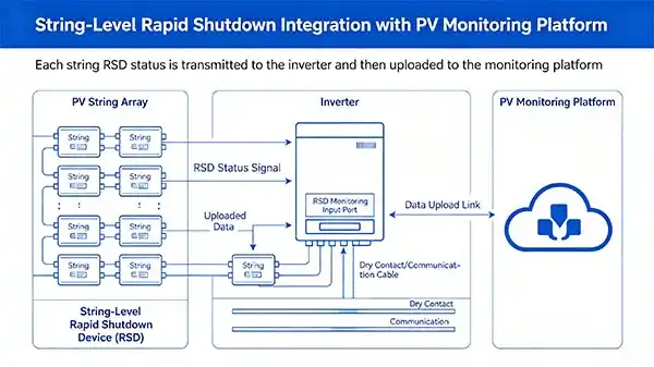
This is the simplest integration method. Many modern inverters include dedicated RSD monitoring input ports. Status signals from each string RSD—typically via dry contacts or communication cables—are transmitted directly to the inverter, which then uploads the data to its native monitoring platform.
For example, Solis has integrated a rapid shutdown transmitter directly into the inverter’s wiring box, eliminating the need for expensive external wiring terminals. The integrated transmitter sends independent signals to each string, ensuring efficient rapid shutdown. This “plug-and-play” approach means no extra wiring, no extra configuration, and no extra time cost.
Advantages: Minimal hardware, simplest wiring, lowest maintenance cost. Applicable scenarios: New plants where the inverter and RSDs are from the same brand or have been thoroughly compatibility-tested.
Standalone RSD Gateway
When inverters are incompatible or a plant already has mixed-brand equipment, a standalone gateway is a more flexible option. A dedicated gateway collects status data from all RSDs via a dedicated communication bus or power line communication (PLC), then sends the data to a cloud monitoring platform over Ethernet or cellular.
The NEP PVG-O is a typical example of this approach. The solution includes a pre-installed NEP gateway and transmitter controller, using a PLC with dual current transformers to ensure stable communication between RSDs and the gateway and accurate current monitoring. System performance and status reports are aggregated on the NEP BDG‑256 monitoring platform. Similarly, the SUNGO RSDi‑2 emphasizes seamless data flow integration with the GT or GTC gateway.
Advantages: Independent of inverter brand, suitable for large plants with mixed-brand equipment. Applicable scenarios: Retrofits of older plants whose inverters do not support RSD monitoring, or commercial plants using multiple inverter brands simultaneously.
PLC Over Power Lines
Power line communication (PLC) uses the existing DC power lines to transmit status signals, requiring no additional wiring. The Tigo RSS transmitter is a representative example: it sends a “keep-alive” signal via PLC to the TS4‑F units. When the transmitter shuts off, the TS4‑F units automatically enter rapid shutdown mode. The PLC specification defined by the SunSpec Alliance further ensures interoperability between different brands, making PLC-based integration feasible across vendors.
However, special attention is required: the RSD communication frequency must not interfere with the inverter’s PLC communication. Additionally, the SunSpec Alliance notes that the rapid shutdown signal is one of several signals that are forced to share the DC power lines, and FCC frequency regulations must be observed.
Advantages: No extra communication cables, simplest installation. Applicable scenarios: Plants with tight rooftop space or difficult cabling, or standardized deployments using a single-brand PLC solution.
Use Devices with Communication Capability
The entire integration depends on the RSDs themselves having communication capability. If an RSD is a “dumb device” (it can receive a shutdown signal but cannot report its status), the monitoring platform will only ever show “unknown.” Selecting communication-enabled RSDs is the first and most critical step.
What to Look For in Product Specs
When procuring RSDs, the product datasheet should explicitly include the following keywords:
-
“Monitoring-ready” or “with communication port”: Indicates the device supports status reporting.
-
Communication protocol: Confirm that the RSD supports at least one of Modbus RTU, Modbus TCP, CAN bus, or the SunSpec RSD standard protocol.
-
Communication interface: Specify whether it uses RS485 terminals, dry contact signal output, or embedded PLC-based communication.
-
Platform compatibility: confirm that there is a published compatibility list between the RSD brand and the chosen monitoring platform (or inverter brand).
The SunSpec standard is currently the most credible guarantee of interoperability in the industry. SunSpec-certified devices have significantly fewer compatibility problems when integrated across brands. Multiple manufacturers—Solis, Tigo, Fronius, and others—have obtained SunSpec RSD certification.
Plan the Communication Network Early
Communication network planning directly determines the feasibility of integration and the long-term reliability of the system. If distance limits or signal interference problems are discovered only after hardware installation, the retrofit cost will far exceed the upfront planning effort. RSD communication networks should be incorporated into the plant design phase from the start.
Cabling Considerations
If using a wired RS485 or dry contact solution, the cable routing must follow these principles:
-
Avoid running parallel to AC power cables: High-voltage interference can corrupt low‑speed communication signals.
-
Use shielded twisted‑pair cable: In industrial environments, shielding significantly reduces the impact of EMI on bit error rates.
-
Cable length limit: For a single string, keep total DC loop length under 160 m; for parallel strings, under 120 m (about 394 ft).
-
Proper grounding: The shield should be grounded at one end only to avoid ground loops.
Addressing and Labeling
Each RSD must have a unique communication address on the network—the foundation for correct device identification by the monitoring platform. For Modbus networks, assign addresses sequentially starting from 1, following the physical layout of the strings.
Equally important is physical labeling on site: each RSD enclosure should clearly display its communication address and corresponding string number. When an O&M technician needs to investigate a specific RSD in the field, they can locate it quickly without searching across the entire roof. On a large commercial rooftop, this labeling is invaluable.
Set Up Alerts and Reports
Device installation and communication connectivity are only the starting point. The real value of a monitoring system comes from configuring alert rules and report templates. Monitoring without alerts is just “watching”; compliance without reports is just “guessing.”
Critical Alerts
The following alert rules should be configured as soon as the monitoring platform goes live:
-
Unexpected RSD shutdown alert: When an RSD changes from “on” to “off” without an expected trigger, send an SMS or email immediately.
-
A communication loss alert is triggered when an RSD has not reported data for longer than a configured timeout, potentially indicating power loss, cable break, or RSD failure.
-
State change event: Every RSD state change should be logged as an event to facilitate later analysis of trigger frequency and root causes.
Note that very short-duration events may not trigger alerts. Some monitoring platforms do not generate alerts for events lasting less than 10–15 minutes. Therefore, when testing rapid shutdown functionality, keep the system in shutdown state for at least 30 minutes to ensure that alerts are reliably generated.
Scheduled Compliance Reports
Compliance audits do not need to be a scramble to gather records on the audit day. Set up the following automated reports on the monitoring platform:
-
Monthly RSD status summary report: Lists all RSDs with statistics for the reporting period—number of shutdowns, total shutdown duration, communication interruptions, etc.
-
The quarterly compliance completeness report contains installation information, device address, firmware version, and status history for each RSD, serving as a compliance archive.
-
The exception event report specifically summarizes all RSD exception events during the period for O&M follow-up.
Export reports in an auditable standard format and archive them in the project document library for at least seven years.
Common Integration Challenges
Even when following best practices, some typical technical challenges can arise during integration. Knowing these challenges and their solutions in advance prevents last‑minute surprises.
Incompatible communication protocols between different brands
This is the most common integration barrier. A plant might use brand A for RSDs, brand B for inverters, and brand C for a monitoring platform, with incompatible protocols among them.
Solutions: Use a protocol conversion gateway as an intermediary; or, from the initial selection stage, insist on SunSpec‑certified devices to maximize interoperability. The SunSpec standard was designed precisely to solve “communication barriers” between multivendor devices.
Signal attenuation over long distances
In large commercial plants, the distance between RSDs and the gateway or inverter can be hundreds of meters. Signal attenuation leads to data loss or frequent communication interruptions.
Solutions: Install RS485 repeaters at the midpoint of the communication path; choose a communication technology that supports longer distances; or use a PLC solution, since PLC over DC power lines generally has better distance performance than dedicated RS485 cabling.
Data errors due to electromagnetic interference
High‑frequency switching of inverters, AC power cables, and nearby heavy equipment can all generate severe electromagnetic interference.
Solutions: Use shielded twisted‑pair cable with proper single‑end grounding; route cables as far as possible from AC cables and inverter enclosures; in extremely noisy environments, consider optically isolated repeaters to break the interference path.
Frequently Asked Questions
Q1: Can I retrofit monitoring to existing RSDs without communication ports?
A: Generally, no. RSDs without communication ports cannot output any status signal. To obtain monitoring capability, you have two paths: replace them entirely with communication‑enabled RSDs; or install independent status sensors in parallel with the output of existing RSDs. In most cases, it is advisable to include communication‑enabled RSDs in a broader inverter‑ or system‑level upgrade.
Q2: Does integrating RSD with monitoring increase cybersecurity risks?
A: Yes, any device connected to a network introduces an additional attack surface. To mitigate risks, take the following measures: ensure the monitoring platform uses TLS‑encrypted connections; regularly update firmware and passwords for all devices; physically isolate the RSD monitoring network from the office network, or use VLAN logical isolation; and enforce role‑based access control (RBAC) for monitoring platform access.
Q3: How much data does an RSD monitoring system generate?
A: Very little. Each RSD typically sends a few bytes of status data per minute. For a plant with 200 string RSDs, the total data per minute is less than 1 KB—no measurable impact on network bandwidth. Bandwidth bottlenecks, if any, lie not in RSD data but in other high‑frequency data collection.
Summary & Next Steps
Integrating string-level RSDs with system monitoring is an investment that simultaneously improves O&M efficiency, safety compliance, and fault response capability. The key is a three‑pronged approach: during equipment selection, prioritize communication‑enabled RSDs and verify protocol compatibility; during plant design, plan the communication network—cabling, addressing, and protection—in advance; after go‑live, configure appropriate alert rules and automated compliance reports.
For system integrators planning new plants, include RSD monitoring in the overall communication architecture from day one to avoid costly retrofits. For O&M managers of existing plants, start with a pilot deployment of monitoring‑enabled RSDs in a critical high‑risk area, validate the benefits, then expand.
Next steps: Assess the needs and constraints for RSD monitoring integration in your current or planned plant. Choose the appropriate integration architecture and equipment supplier. Develop a complete deployment plan that includes communication testing, alert configuration, and training.