 English
 Bahasa Melayu
 Suomen kieli
 عربي
 Português
 Français
 Pусский
 Español

How does the remote signaling contact on a Type 2 DC SPD work?


If you have seen “remote signaling contact” on a Type 2 DC SPD datasheet or on the SPD enclosure itself, you may be unsure what it actually does. In short: it is a dry-contact output linked to the SPD’s status mechanism. It converts the binary state of “normal” or “needs inspection/replacement” into an open or closed contact signal for an external monitoring system. It does not measure surges, record waveforms, or act as a communication protocol port. Understanding this boundary is essential for designing monitoring circuits correctly and avoiding false alarms or missed alarms.
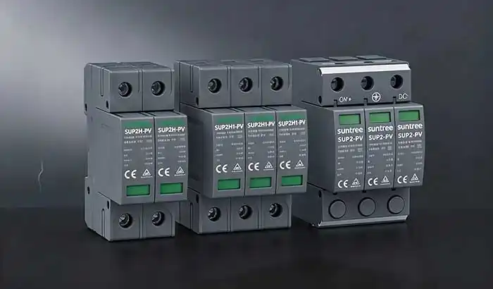
Local Status and Remote Status Serve Different Users
A Type 2 DC SPD usually provides two forms of status feedback, and they serve two different groups of users.
The Visual Status Window
The local status window—typically green/red—is for people standing at the installation. Green means the module is still in service. Red means the internal thermal disconnect has operated or the module has failed and needs replacement. Its value is that it is immediate and intuitive. It requires no external power supply or signal circuit. When a technician opens a combiner box or the DC side of an inverter, the status window is the first thing to confirm.
The Remote Signaling Terminal
The remote signaling terminal is for systems that are not physically at the site. It converts the position of the same status mechanism into the open/closed state of an electrical contact. The “SPD fault” alarm that an operator sees on a SCADA screen in the control room ultimately originates from this terminal. Both the window and the contact share the same physical criterion, but they serve completely different purposes: the window supports site inspection, while the contact supports centralized monitoring.
What Information Does the Remote Contact Actually Provide?
The remote contact does not output an analog value or a digital communication message. It provides a binary status.
Most Type 2 DC SPD remote terminals use a COM / NO / NC three-terminal arrangement. This is essentially a single-pole double-throw (Form C) dry contact. “Dry” means the contact itself does not output a voltage—it is simply a switch driven by the SPD status mechanism. The PLC or monitoring system must provide its own detection voltage.
Typical logic is as follows:
-
Normal state: NC–COM remains closed, and NO–COM remains open. If the monitoring circuit uses the NC–COM “fail-safe” connection, the PLC digital input reads ON, corresponding to “SPD normal.”
-
Module abnormal / inspection required state: When the SPD module enters a failed state due to aging, thermal disconnection, or severe surge impact, the mechanism changes position: NC–COM opens, and NO–COM closes. A circuit using NC–COM therefore loses the closed signal, the PLC input changes to OFF, and an alarm is triggered.
There is a design point that is easy to overlook: the “normally closed” logic of NC–COM naturally provides open-circuit detection. If the signal wire is accidentally cut or a terminal works loose, the circuit also appears “open,” and the system receives an alarm. With a NO–COM connection, the same condition may appear normal. For unattended combiner boxes, this directly determines whether a fault is “seen” or “hidden.”
However, it is not a complex communication protocol. There is no Modbus, no address, and no multi-byte status word. There is only “closed” and “open.”
Where Can the Signal Be Sent?
The compatibility of a dry contact comes precisely from its simplicity. Any device that can read the open/closed state of a passive contact can receive this signal.
SCADA or Monitoring Input
In large PV plants, SPD remote contacts inside combiner boxes are usually connected to the digital inputs (DI) of a combiner-box monitoring unit or data logger, and then uploaded to SCADA via RS485 or Ethernet. SCADA maps that DI point to an “SPD status” remote signal. It displays green under normal conditions and changes color with a timestamp when an alarm occurs.
Alarm Panel
In smaller C&I sites or sites without full SCADA, the contact can directly drive a local alarm relay or indicator lamp. Pay attention to the contact switching capacity: typical Type 2 DC SPD remote contacts are rated in the range of ≤125 V DC / ≤1 A, depending on the datasheet. When directly driving a larger relay coil or sound-and-light alarm, confirm that the capacity matches. If necessary, use an intermediate relay.
Remote Maintenance Notification
Once the signal enters a monitoring platform, it can be further configured as a work-order trigger. When the SPD status bit of a certain combiner box changes, the system automatically generates a “replace SPD module” maintenance task, including the site name, combiner box number, and SPD location. This turns a contact change into an actionable O&M activity.
What the Remote Contact Does Not Tell You
This is the part most likely to cause misunderstanding during engineering selection and commissioning. The value boundary of the remote contact is very clear. Expectations beyond that boundary can lead to incorrect decisions.
It Does Not Measure Surge Magnitude
The contact only reflects whether the status mechanism has operated. It does not reflect “how large the last surge was.” An SPD’s MOV may have experienced multiple impulses that did not trigger thermal disconnection but caused gradual degradation. The contact may still show “normal” because the thermal disconnect has not operated. The remote contact cannot replace a professional assessment of MOV remaining life.
It Does Not Identify the Source of the Surge
The contact may change state because of a lightning strike, but it may also change because of repeated small transients, continuous system overvoltage, thermal stress inside the enclosure, or natural MOV aging. The contact does not distinguish “why it failed.” It only reports “failed or needs inspection.” Treating a contact alarm as equivalent to “lightning damage” can point fault analysis in the wrong direction. For a deeper look at why a DC SPD status window can change color even on a clear day with no lightning activity, see Why Does a DC SPD Status Indicator Change Color Without a Lightning Strike?
It Does Not Replace Physical Inspection
A closed NC–COM circuit indicates that the signal path and contact mechanism are in the expected normal position, but it does not prove that the SPD’s varistor still has full surge withstand capability. The remote contact solves “when to go and check,” not “what to check.” Site inspection is still required to confirm module appearance, window color, and, when necessary, MOV status using dedicated test methods.
Why Remote SPD Status Matters on Large PV Sites
On a 100 MW-scale ground-mounted PV plant, the number of DC-side SPDs can easily reach thousands, distributed across hundreds of combiner boxes. If relying only on manual inspection, the interval between the first SPD failure and its discovery during inspection could be weeks or even months. During that window, the corresponding string or combiner box is effectively without surge protection.
The role of the remote contact is not to eliminate inspection. It is to change how inspection is triggered: from “periodically scan everything” to “alarm-driven targeted inspection.” SCADA tells the O&M team, “Check the SPD in combiner box No. 12, array No. 3.” The technician goes to the right location with the right spare part. For rooftop distributed assets, this difference is even more significant—every rooftop visit has a cost, and the contact reduces unnecessary site visits.
What Should Be Documented During Commissioning?
Commissioning a remote contact is not finished once the wire is connected and a signal is seen. The following information must be fixed in the commissioning documentation; otherwise, later O&M or system upgrades can easily lead to inverted logic.
Contact state logic. Clearly record the terminal combination used (COM–NC or COM–NO) and whether “normal” corresponds to PLC input ON or OFF under that logic. Different manufacturers may define NO/NC under “normal” and “fault” conditions differently. Do not infer only from the terminal letters.
Terminal numbering. Record the actual terminal markings on the SPD side (for example, COM = 11, NO = 12, NC = 13) and the channel number connected to the monitoring module. The wiring diagram inside the enclosure should match the actual hardware.
Monitoring system label. In SCADA or the monitoring unit, the DI point label should include site, inverter/combiner box number, and SPD location. Avoid generic alarm names such as “SPD fault” that cannot be located.
Alarm name and priority. Define the display text of the alarm on the HMI, whether audible/visual indication is required, and whether a maintenance work order should be generated automatically. The contact itself is only a signal source; alarm behavior rules must be defined on the monitoring side.
Frequently Asked Questions
Does every Type 2 DC SPD have a remote signaling contact?
No. The remote signaling contact is an optional feature of Type 2 DC SPDs, usually distinguished by a model suffix or an additional ordering code (such as “/F” or “S” option). Basic models may have only a local status window. If the monitoring concept requires SPD status to be uploaded, you must confirm at the model level that this option is included. Do not assume that “all Type 2 SPDs have it.”
Can an SPD remote contact connect to a BMS or SCADA system?
Yes, and this is one of its main applications. The prerequisite is that the receiving side provides dry-contact digital inputs (DI) or can convert the passive contact into a system-readable signal through an intermediate relay. The SPD contact itself does not supply power. The BMS or SCADA DI module must provide the detection voltage circuit. Before wiring, confirm two things: whether the contact rating covers the circuit voltage/current, and whether the selected NO/NC logic is consistent with the monitoring system’s fail-safe strategy.
Does the contact show how strong the surge was?
No. The remote contact is a status switch, not a surge sensor. It only reports whether the SPD has entered a state that requires intervention. It does not record surge amplitude, count, or waveform. Using the contact alarm as a “lightning intensity indicator” goes beyond the engineering definition of this signal.
Summary and Monitoring Application
The remote signaling contact on a Type 2 DC SPD is essentially a dry contact for status output: the SPD status mechanism changes position, the contact changes state, and the monitoring system reads binary information—either “normal” or “attention required.” Its strength is centralizing the health status of SPDs distributed across hundreds of combiner boxes onto a single SCADA screen, so O&M teams do not have to wait until the next inspection to discover that protection is missing. It is not designed to measure surges, record events, or replace site inspection, and it should not be required to do so.
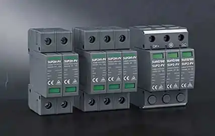
If you are selecting a Type 2 SPD with remote signaling for the DC side of a PV system, confirm the contact option and wiring logic based on the monitoring system’s DI type, fail-safe strategy, and installation environment. You can view specific models with remote signaling terminals and contact specifications on the Type 2 SPD models with remote signaling terminals page.