 English
 Bahasa Melayu
 Suomen kieli
 عربي
 Português
 Français
 Pусский
 Español

How does a battery breaker trip during BESS startup?


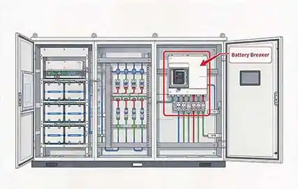
When a battery breaker trips during BESS startup, the first question is not “what is wrong with the breaker?” but “at exactly which point in the startup sequence did it trip?” The same breaker can trip at closing, when the PCS starts, or after the BMS enables discharge, and each timing points to a different fault domain. Startup also introduces variables that normal operation does not exercise simultaneously—pre-charge, DC-link capacitor inrush, contactor timing, and communication interlocks. The most efficient approach is to use the trip timeline and event logs to identify the first deviation from the intended startup sequence before suspecting the breaker itself. For a broader overview of how a battery breaker is applied in BESS DC circuits, see the Battery Breaker pillar page.
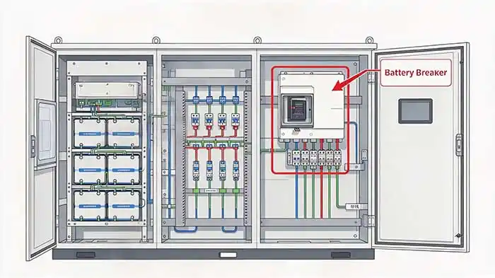
The Timing of the Trip Is the First Useful Clue
Trip Immediately After the Breaker Closes
If the breaker trips as soon as the handle is closed—before the PCS or BMS advances to the next step—the first suspect is instantaneous current exceeding the instantaneous trip threshold, not sustained overload. The classic mechanism is PCS DC-link capacitor charging inrush: an uncharged capacitor behaves like a low-impedance load at the instant of closing, and a battery with low internal resistance can deliver a very high current in a very short time. If the system has no proper pre-charge circuit, or if the pre-charge resistor or contactor fails to limit current effectively, the inrush peak can trigger the breaker’s magnetic trip or instantaneous protection. This pattern is characterized by no AC load connected, correct polarity, and a trip at closing, while the BMS may record a short-duration overcurrent or short-circuit event. Reverse polarity, a cable or busbar short to enclosure, or foreign conductive objects left in the cabinet can also cause a closing trip, but these usually show more direct short-circuit signatures and require insulation and continuity checks with the system de-energized.
Trip When the PCS Starts
If the breaker closes and the system reaches a standby state, but trips when the PCS begins startup, DC bus establishment, or the pre-charge sequence advances, the focus should shift from “closing inrush” to PCS-side DC bus condition and pre-charge process. If the PCS DC-link capacitors are not pre-charged close to battery voltage, or if pre-charge times out, or the pre-charge contactor feedback is abnormal, the PCS may trigger DC bus abnormality or overcurrent protection during startup and then trip the battery breaker through an interlock. PCS DC bus voltage measurement errors, residual bus voltage not discharged, aging pre-charge components, or communication commands not arriving in the correct sequence can all appear at this stage. BMS logs in this case often show sequence-type abnormalities—pre-charge timeout, bus voltage not reaching the expected value, or contactor state inconsistent with command—rather than a brief spike at the instant of closing.
Trip After the BMS Enables Discharge
If the breaker remains closed and trips shortly after the BMS issues the discharge enable command, the fault appears after the discharge circuit is actually loaded or after the main contactor state changes. Possible directions include abnormal cell conditions causing cluster-level current anomalies, main contactor contact sticking or bouncing distorting the current waveform, circulating current or current-sharing loss when multiple clusters are paralleled, and BMS actively requesting disconnection due to cell overvoltage, undervoltage, or temperature protection. In this case, the breaker may not have “sensed a fault and tripped” on its own; it may have executed a trip command from the BMS or upper-level controller. Therefore, the protection-action records in the BMS event log are more diagnostic than the breaker’s own trip flag.
What the BMS and PCS Event Logs Can Reveal
A common trap in startup log analysis is to treat the last alarm as the cause. In reality, the first event that deviates from the expected sequence is usually the cause, while later alarms are downstream consequences. The BMS may report pre-charge failure, and the PCS may simultaneously show DC bus abnormality, but both may be manifestations of the same upstream condition. The correct method is to align BMS state transitions, pre-charge contactor commands and feedback, PCS DC bus voltage records, and protection action timestamps in chronological order, then find the first point where the startup sequence departs from the designed path.
Key log fields to compare include:
-
Overcurrent or short-circuit events: Check how many milliseconds after closing they occurred, how long they lasted, and whether the peak has inrush characteristics—very short, without sustained overload—or sustained short-circuit characteristics.
-
DC bus status: Whether the PCS-recorded bus voltage reached the expected pre-charge level before the trip, or remained in a clearly low range.
-
Pre-charge status: Whether the BMS or PCS reported pre-charge timeout, pre-charge relay/contactor failure, or pre-charge resistor circuit abnormality.
-
Interlock and dry-contact states: Whether fire protection, emergency stop, door access, insulation monitoring, or other external interlocks changed state during the startup sequence and triggered protective disconnection. In some systems, a pressed emergency stop or an abnormal interlock circuit can directly cause the battery breaker to trip immediately after closing.
If an alarm appears after the startup sequence has already stopped, it is likely a result rather than a cause and should not be the primary basis for replacing components.
Check Whether the Problem Is Upstream or Downstream of the Breaker
The fault domain can be roughly divided by the breaker into the battery rack side, the DC bus and PCS side, and the connection path.
Battery Rack Side
The battery rack side focuses on whether there is a sustained abnormal current path inside the cluster: severe cell inconsistency, a cluster fuse close to blowing, abnormal cluster contactor contacts, reverse cluster connection, or inter-cluster circulating current. For a closing trip, segment isolation is an effective way to distinguish the battery side from the PCS side: disconnect the cluster from the DC bus, check the battery cluster side insulation and circuit condition separately, and then restore step by step.
DC Bus and PCS Side
The DC bus and PCS side centers on whether the pre-charge circuit actually performed its function. When PCS DC-link capacitance is large, closing inrush can be significant without effective pre-charge; after pre-charge is complete, the bus voltage should be close to the battery voltage. If the measured value deviates significantly, the problem may be in the pre-charge resistor, pre-charge contactor, or the PCS bus capacitor itself. Internal DC bus short circuits or power module abnormalities in the PCS are less common, but should be included after pre-charge and cable issues are ruled out.
Cable and Busbar Connections
Cable and busbar connections are an often-underestimated part of startup tripping. The high current at startup amplifies contact resistance at poor connections: terminals not tightened to torque, oxidized copper busbar contact surfaces, poor cable crimping, or loose lugs can all cause local overheating, voltage abnormality, or protection operation at the instant of high current. Visual inspection for terminal discoloration and infrared temperature measurement are quick screening methods, but final verification requires checking connections against the manufacturer’s torque values. For layout and coordination background, see where a battery breaker should be installed in a BESS DC circuit.
Breaker Settings and Application Conditions Matter
A common but incorrect reaction to a startup trip is to “install a breaker with a larger rating.” The breaker’s instantaneous trip characteristics and short-circuit interrupting capability must match the system design values, including the maximum short-circuit current the battery cluster can deliver, the PCS DC bus capacitance, and the startup inrush signature. Arbitrarily increasing the rating may prevent the breaker from clearing a real short-circuit fault in time and may weaken protection selectivity. The correct approach is to verify whether the model’s trip curve and instantaneous setting are consistent with the startup inrush envelope and short-circuit level given in the design documents, and to confirm that its DC interrupting capability meets the application requirements. If you need help checking the breaker against your startup inrush envelope, DC bus capacitance, and available short-circuit current, contact our BESS technical support team before changing the breaker rating.
What Physical Signs Should Be Checked at the Battery Breaker?
Physical inspection can indicate whether the breaker has already experienced abnormal stress and should not simply be reset. Check for discoloration or insulation charring around terminals, which indicates loose connections or high contact resistance causing local overheating. Look for cracks or deformation of the enclosure, sticking or abnormal feel in the handle mechanism, and arc traces in the arc chamber area. If these signs are present, even if the root cause is in the external circuit, the breaker itself should be evaluated or replaced according to the manufacturer’s requirements.
Why Repeated Resetting Is Not a Diagnostic Method
When the breaker trips again immediately after startup, repeated closing, holding the handle closed, or temporarily bypassing the breaker will inject energy into the circuit repeatedly while the fault remains. This can damage the breaker contacts, battery main contactor, DC connectors, and PCS DC terminals, and can expand the fault range if a short circuit or insulation defect exists. The only reasonable precondition for a diagnostic reset is that a clear, verifiable problem has already been found and corrected, and the manufacturer’s procedure allows one controlled verification restart. Even then, the original event timeline and alarm states should be recorded before resetting, rather than using repeated operations to “test for” a non-tripping result. General BESS breaker troubleshooting resources can help frame the investigation, but they do not replace the site-specific timeline and logs.
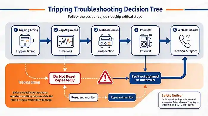
Frequently Asked Questions
Why does the breaker trip only during startup but not normal operation?
Startup is the only time the system simultaneously exposes the breaker to DC-link capacitor inrush, pre-charge contactor sequencing, BMS-to-PCS communication handshakes, and interlock state changes. Normal operation does not repeatedly charge an uncharged DC bus or transition contactors under those conditions. A breaker that is marginally applied—or a pre-charge circuit that is aging—may pass normal operation but fail at the one moment when current and timing coincide.
Can the PCS cause a battery breaker startup trip?
Yes. The PCS can cause a battery breaker trip indirectly by reporting DC bus abnormality, pre-charge timeout, or overcurrent during startup and then issuing an interlock or trip command. The breaker may be functioning correctly as the executing device while the root cause is in the PCS pre-charge circuit, DC bus measurement, or startup sequence logic.
Will using a larger breaker solve repeated startup trips?
Usually not. A larger breaker may mask the symptom temporarily while allowing higher inrush or fault current to stress capacitors, contactors, and cables. It can also reduce protection coordination and delay clearing of a real short circuit. The correct fix is to identify whether the trip is caused by inrush, pre-charge failure, insulation fault, contactor timing, or a protection setting mismatch—and then correct that condition.
What Information Should Be Sent to Technical Support?
When on-site troubleshooting cannot locate the root cause without disassembling equipment, the quality of information sent to technical support directly determines response efficiency. The following framework is recommended:
-
Trip timing: Immediately after closing, at PCS startup, or after BMS enables discharge, with relative timing where possible—for example, “approximately 200 ms after closing.”
-
BMS and PCS log exports: Raw event records with timestamps, prioritizing state-transition sequences rather than screenshots of final alarms only.
-
Breaker information: Model, rated current, trip curve/settings, and whether a trip indicator or fault record is available.
-
Load and contactor status at startup: Whether the PCS was pre-charged, DC bus voltage readings, and whether the main contactor command and feedback were consistent.
-
Site photos: Breaker terminals, DC busbar connection points, cable routing inside the cabinet, and BMS/PCS alarm screens photographed from a safe distance.
-
Recent changes: Whether battery clusters were added, PCS or cables were replaced, or BMS protection settings or startup sequence parameters were adjusted.
Startup tripping is fundamentally a timing-alignment problem: first fix “when it tripped,” then use the logs to find the first event that deviated from the designed sequence, and then perform segmented verification along the battery cluster—DC bus—PCS path. The breaker may be the last element executing a protection command, or it may be the component absorbing an inrush or pre-charge defect. Without completing the timeline and log analysis, replacing the breaker usually only hides the path along which the fault migrates. When replacement or selection is eventually required, confirm the application against a battery breaker for energy storage systems rather than simply increasing the rating.