 English
 Bahasa Melayu
 Suomen kieli
 عربي
 Português
 Français
 Pусский
 Español

How to troubleshoot a solar string with no output while the PV fuse remains intact


You open the combiner box, pull the PV fuse, and put the multimeter on continuity. It beeps. The fuse is good. You reinstall it, close the disconnect, and the string current is still zero. This is a common field scenario, and it is one of the easiest to turn into a loop of replacing fuses. The problem is not the fuse itself. The fuse is only one node on the DC path; it is not proof that the entire path is healthy.
A string that has stopped contributing is, in most cases, an open circuit, not a simultaneous failure of all modules. The open circuit can be in the fuse, the fuse holder, the PV connectors, the string cable, the combiner box terminals, or even the inverter DC input terminals. A good fuse only proves that one short section of conductor is not broken. It does not prove that current has a complete path to flow.
This article starts from the specific symptom: the PV fuse looks good but the solar string has no output. It works along the DC path section by section. It does not repeat the topic of what causes a DC fuse to blow repeatedly in a solar string. Instead, it addresses a more practical field question: when the fuse should not be treated as the culprit, where should the inspection focus go?
A Fuse Can Look Normal Without Proving the Circuit Is Healthy
A continuity beep, or no visible break in the fuse element, only proves that the fuse element is conductive at the moment of testing. It does not prove three things: that the contact resistance between the fuse and the holder is low enough, that the connection between the holder and the terminal remains stable under load current, and that the rest of the DC circuit beyond the fuse is complete.
PV DC circuits have a characteristic that often misleads people: in an open-circuit condition, you can still measure near-normal open-circuit voltage across the break. Because the modules are a power source under illumination, as long as one side of the break is connected to the positive or negative side of the string, the multimeter will read voltage. Voltage is present, but current has no return path, so string output is zero. Therefore, "voltage at the fuse" and "the fuse lets current through" are two different things.
A more hidden condition is elevated contact resistance that has not yet become a complete open circuit. When contact resistance degrades from a normal value (for example, ≤50 mΩ) to 300 mΩ or more, the circuit may still be "continuous" at low load or in a cold state, but the voltage drop becomes significant near operating current, and thermal cycling can further degrade it to an open circuit. The fuse itself is good, but the holder may not be able to pass current under load.
Therefore, the first step is not to retest the fuse repeatedly, but to treat the fuse and the fuse holder as one assembly.
Check the Fuse and Fuse Holder as One Assembly
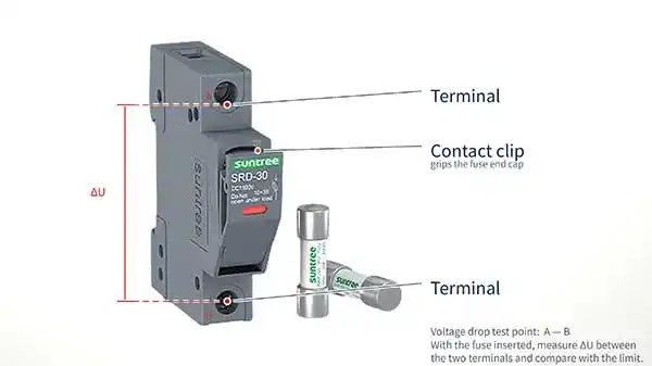
Fuse Link Condition
Testing continuity with the fuse still in the holder has a trap to watch for: if there is a parallel conductive path inside the holder or in adjacent circuitry, the multimeter may read continuity through a "detour," making you think the fuse is good. A more reliable method is to remove the fuse from the holder after safe isolation and test it separately. A continuous beep only means the fuse element is not broken. If the reading is unstable, intermittent, or not close to zero resistance, replace the fuse directly. Do not reinstall it "just to try."
Holder Contact Pressure
The clamping force of a fuse holder is maintained by spring contacts. Thermal cycling—temperature rise under high irradiance during the day and cooling at night—gradually causes the contacts to lose their initial pressure, and contact resistance rises. Once the contact leaves "do not spring back," the fuse may still sit in the holder, but the actual contact area is no longer sufficient to carry string current.
Without a dedicated micro-ohmmeter, one practical field criterion is DC millivolt drop under load: when the string has operating current, measure the voltage across the fuse holder (or across the contact points between holder and fuse). A healthy connection typically shows a drop in the tens of millivolts. If the drop reaches hundreds of millivolts or more, the holder is already a significant resistance in the circuit and must be replaced, not cleaned and returned to service.
Terminal and Contact Surface Condition
Open the fuse holder and inspect the contact leaves and terminal surfaces. Normal metallic luster is the baseline. Blackening, green or white deposits, pitting, or burn marks all indicate that this point has been hot. For corroded terminals in a combiner box, in-situ cleaning is often not a reliable repair; corrosion has already changed the geometry and material of the contact surface. Replacing the terminal or fuse holder is the more thorough approach. Also check terminal screw tightness—thermal cycling gradually loosens terminals that were originally tightened to torque, and this is a common starting point for intermittent open circuits.
The key judgment here is: a fuse passing a continuity test does not mean the fuse holder passes a load test. If the holder has a thermal history or questionable contact pressure, skip the step of "try another fuse" and replace the holder as the target component. For a broader review of string-level protection and holder selection, see solar DC protection solutions for combiner boxes.
Follow the String Path Beyond the Fuse
Once the fuse and holder are ruled out, the inspection scope extends along the DC path on both sides: upstream from the combiner box fuse holder (string side) are the PV connectors, string cable, and module junction boxes; downstream (inverter side) are the combiner box output terminals and the inverter DC input. A string open circuit can occur in any of these sections.
PV Connectors
PV connectors are among the highest-failure-rate nodes in the field, and the reasons are not mysterious: poor crimping, cross-brand mating, worn locking clips, and seal failure with water ingress can all make a connector that "looks plugged in" electrically unacceptable.
Several checks can provide signals without disassembling the connector. Listen for the click: if there is no clear click when mating, or if there is still movement when you gently pull back after the click, the locking clip is not fully engaged and contact pressure is unreliable. Look at the housing: discoloration, gloss, melt spots, or internal moisture point to high-resistance heating or moisture ingress; such a connector should not be re-mated. Measure load voltage drop: if the string still has partial current (even intermittent), measure the voltage drop across the mated connector. A healthy PV connector should show essentially zero voltage drop under load; any measurable, stable drop means internal contact resistance is dissipating power.
For a string with completely zero current, voltage drop cannot be measured once the connector is open. In this case, use sectional voltage measurements to locate the fault: measure DC voltage step by step from the combiner box toward the modules. The section where voltage disappears is where the open circuit is located.
String Cable
Open circuits in string cable often have visible clues: abrasion at roof edges, insulation damage at tray sharp edges, rodent chewing, or cable sagging against the roof or metal after cable ties age. But there is a condition where the appearance is normal and the circuit is electrically open: excessive bending during installation or maintenance can fatigue and break the internal copper conductor while the outer insulation remains intact. This type of break can only be located by sectional measurement or bisection—measure voltage at the midpoint of the string, determine whether the break is in the half closer to the combiner box or the half closer to the modules, then repeat within the faulty half until the break is narrowed to between two adjacent nodes.
Combiner Box Terminal
The string input terminal in the combiner box is another node easily masked by "the fuse is good." A fuse holder passing a test does not mean the combiner box terminal behind it is tight. Thermal cycling and insufficient initial torque gradually back out terminal screws. The contact surface may still conduct in a cold state, but under temperature rise or vibration it behaves as an intermittent open circuit.
After isolating the combiner box and verifying absence of voltage, perform a pull test on the input terminal of the affected string: gently pull the conductor to confirm it is not loose or pulled out of the terminal. If the conductor can be pulled out, the terminal has failed and the connection must be remade to manufacturer torque or the terminal replaced. Also inspect the insulation around the terminal for heat shrinkage, discoloration, or scorch marks.
Inverter DC Input
If everything from the combiner box side to the fuse holder passes, but string current still disappears after the combiner box output, the problem may be at the inverter DC input terminals or the MPPT input itself. An inverter reporting "no DC input" or zero current on a string does not automatically mean a string-side fault. Loose DC terminal blocks inside the inverter, poor contact in internal string protection holders (if the inverter has independent string protection), or even an MPPT input channel fault can all present as "one string is dead."
When checking the inverter side, first confirm that the inverter is displaying true zero current rather than a metering or communication error. Use a DC clamp meter directly on the inverter DC input cable (clamp only one conductor) and compare with the inverter display. If the clamp meter reads current comparable to neighboring strings while the inverter displays zero, the problem is in the inverter metering or MPPT input channel, not in the string DC path. If the clamp meter also reads zero and voltage at the combiner box output terminals is normal, the open circuit or high-resistance point is between the combiner box output and the inverter input, or at the inverter internal DC terminals. If the inverter-side reading is ambiguous, contact our technical support team with the clamp-meter and display readings before replacing string components.
What Can Neighboring Strings Tell You?
In the field, the most useful reference for a "dead string" is not the nameplate data or temperature-corrected calculated value, but the readings of adjacent strings on the same MPPT input, with the same orientation and tilt, at a similar time.
A string that has stopped contributing usually appears as a repeatable "step" on the combiner box or inverter: total output drops by an amount roughly equal to that string's share of the total string count, while other strings' curves continue to follow irradiance. If adjacent strings also drop at the same time, the problem is more likely a common cause—shading, soiling, inverter power limiting, or irradiance change—rather than a single branch open circuit.
When comparing under the same irradiance, open-circuit voltage is an effective tool for comparing the integrity of the series circuit. Open-circuit voltages of adjacent strings in the same array, measured within a short time, should agree within a few percent. A string reading near zero volts points to a complete open circuit in the series loop. A string reading a clean fraction of the neighboring string (for example, one-half or two-thirds) points to a whole module being bypassed or missing from the loop, rather than a simple fuse or connector open circuit.
Current comparison is used to distinguish whether the break is before or after the measurement point. If a string shows near-normal open-circuit voltage at the combiner box but zero load current, the series loop itself is statically complete, and the open circuit or high-resistance point is downstream of the measurement point—the fuse holder, disconnect switch, or the path from combiner box output to inverter. Conversely, if voltage at the combiner box is already abnormally low or zero, the break is inside the string or upstream.
Neighboring string comparison cannot replace sectional measurement, but it can narrow the search from "the entire string" to "upstream or downstream of the combiner box" within a minute or two.
Use the Failure Pattern to Narrow the Search
The time behavior of the fault often points to a specific node more effectively than a single measurement.
Completely no output, never recovered. This is the "cleanest" open-circuit signal. When the fuse is intact, focus on excluding the DC path section by section: fuse holder contact, PV connectors, cable, combiner box terminals, inverter input. A complete open circuit usually has a definite physical break, and bisection or sectional voltage measurement can locate it efficiently.
Intermittent recovery. The string sometimes has current and sometimes zero, or it recovers after gently touching a certain point and disappears again later. This pattern strongly points to high-resistance connections rather than a complete break: insufficient fuse holder contact pressure, loose terminal screws, worn PV connector locking clips that have not fully separated, or a partially broken cable. The danger of intermittent faults is that "it works after wiggling it with the multimeter" creates the illusion that the problem is solved, while the contact surface continues to degrade.
Appears after specific weather. Zero output or insulation alarms after rain or morning dew point to moisture ingress. Water entering PV connectors or fuse holders can cause corrosion, leakage, or degradation of contact surfaces. If the fault has a repeatable time correlation with rainfall, the inspection focus should be on connector seals, combiner box door gaskets, and cable entry waterproofing—not on repeatedly suspecting the fuse.
Appears suddenly after maintenance. A "dead string" appearing after cleaning, module replacement, combiner box inspection, or inverter work should first be checked on the human intervention side: whether the disconnect switch is fully closed, whether PV connectors are truly seated with an audible click, whether combiner box terminals were knocked loose during work, or whether polarity was reversed. Open circuits after maintenance often have a clear location, and if a disconnect switch or connector was operated under load, contact damage may also be present.
When the Fuse Should Not Be Blamed
The most common incorrect reaction to "string no output" is: the fuse tests continuous, reinstall it, still no output, so replace it with a new fuse. If the new fuse still "does not work," or the same symptom appears again after a period of time, continuing to replace fuses is treating the symptom as the fault.
The main protection target of a PV fuse is reverse current: when one string in a parallel array short-circuits, the remaining strings feed current into the fault point, and the fuse is responsible for interrupting that reverse feed path. Therefore, if the fuse has actually blown, it points to a fault inside or downstream of the string it protects, not to the fuse holder itself being "bad." Replacing the fuse repeatedly before the fault is cleared only reconnects the fault to the system on the next close.
But when the fuse is intact and the string has no output, the logic is reversed: the fuse has already proven that it is not the open-circuit point, and continuing to work around it will not change the result. At this point, check contact quality by treating "fuse—holder—terminal" as one assembly, then shift the inspection focus to connectors, cable, and the downstream path. Continuity of the fuse is not a reason to keep replacing fuses. When replacement is actually required, select a correctly rated PV fuse from our product range rather than repeating the same part blindly.
Frequently Asked Questions
Can a PV fuse fail without visible damage?
Yes. A break in the fuse element is not always accompanied by a blackened housing, deformation, or obvious deposits on the inside of the glass/ceramic body. Microcracks or localized element failure can occur under low overcurrent or mechanical fatigue, with a completely normal appearance but failed continuity. This is why a fuse cannot be judged by visual inspection alone; it must be electrically tested. And the electrical test must be performed with the fuse removed from the holder and parallel paths excluded; otherwise, "continuity" may come from a bypass rather than the fuse element itself.
Can a bad fuse holder stop the string even if the fuse is good?
Yes, and this is one of the most overlooked nodes in "fuse is good but string has no output." Loss of spring force in the holder contacts, oxidized contact surfaces, or loose terminals can make the holder exhibit high resistance or even an open circuit under load. The fuse itself can pass a continuity test, but there is no reliable current path between the holder and the fuse. The criterion is not whether the holder "looks burned," but voltage drop or contact resistance under load: a healthy holder has very little drop at string current; a measurable drop means the holder is already limiting current.
Can a loose PV connector cause zero string output?
Yes. A PV connector that is not fully locked, poorly crimped, or has a worn locking clip may still appear plugged in, but the electrical contact area is insufficient to carry current. Under light load or open-circuit voltage measurement, everything may "look normal," but once the circuit is closed or current rises, the high-resistance joint can limit or even interrupt current. Typical clues include no click when mating, movement when gently pulled back, discolored housing, or measurable voltage drop under load. For connectors that have already shown thermal damage or water ingress, do not re-mate them; replace both halves.
Summary for Field Troubleshooting
When the fuse is intact but the string has no output, the core of troubleshooting is not the fuse but the integrity of the entire DC path. The sequence can be summarized as follows: first confirm true fuse continuity outside the holder; then check the fuse and holder as one assembly for contact pressure, terminal tightness, and load voltage drop. If the assembly passes, inspect the string side for PV connector locking, housing thermal history, load voltage drop, and visible cable damage. If no break is found on the string side, move to the combiner box output terminals, inverter DC input terminals, and MPPT input channel.
Comparison of voltage and current with neighboring strings under the same irradiance is used to quickly determine whether the open circuit is upstream or downstream of the measurement point. The time pattern of the fault—completely no output, intermittent recovery, weather-related, or appearing after maintenance—is used to narrow the search to the most likely physical node. The fuse should not be repeatedly replaced just because "the string has no output." It should be tested, ruled out, and then the inspection should continue downstream along the DC path.