 English
 Bahasa Melayu
 Suomen kieli
 عربي
عربي  Português
 Français
 Pусский
 Español
How to Test a DC Surge Protection Device Before Installation?


Installing a DC surge protection device (SPD) into a solar combiner box or distribution panel without testing it first is a gamble you don't want to take. A faulty SPD—damaged in transit, degraded from storage, or simply defective from the factory—won't protect your expensive inverter, charge controller, or PV strings when a surge hits. Taking just a few minutes to perform pre-installation tests can save you hours of troubleshooting down the line and prevent equipment damage that costs far more than the SPD itself.
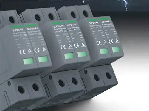
This guide walks you through a practical, step-by-step testing process—from the simplest visual checks to more advanced measurements—so you can verify your DC SPD is ready for service before it goes into the combiner box.
Start with the Visual Inspection – What to Look For
Before you pick up any test instrument, inspect the SPD with your eyes. Visual inspection is the fastest and most accessible first line of defense against installing a damaged device.
Physical Damage: Examine the housing carefully. Look for cracks, deformation from impact, burn marks, charring, melting, bubbling, or discoloration such as yellowing or browning of the plastic casing. Any of these signs indicates the SPD may have suffered an overload or physical stress during shipping.
Terminal Condition: Check the connection terminals for oxidation, corrosion, or damaged threads. Terminals should be clean, tight, and free from discoloration or black residue. Damaged terminals can cause high-resistance connections that generate heat and compromise the SPD's performance.
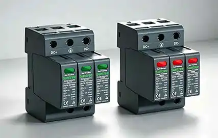
Indicator Window: Most modern DC SPDs feature a status indicator window on the front or top of the device. The color coding is typically straightforward:
-
Green – The SPD is functioning normally
-
Red – The SPD is damaged and needs immediate replacement
-
Yellow/Orange – Performance limit reached; replacement recommended soon
If the indicator shows red before installation, reject the device immediately.
Labeling: Verify that the model number, rated voltage (Uc), nominal discharge current (In), and maximum discharge current (Imax) match your design drawings and procurement specifications. Installing an incorrectly rated SPD is a common but preventable mistake.
Next – Use a Multimeter for a Basic Go/No-Go Test
Once the visual inspection passes, the next step is a simple electrical test using a digital multimeter. This test checks whether the internal MOV (metal oxide varistor) has been damaged—specifically, whether it has shorted out.
Safety First: Always perform this test with the SPD removed from any circuit and completely de-energized. Never test an SPD that is connected to a live system.
What You Need: A digital multimeter capable of measuring resistance at high ranges—set it to the 200kΩ or 2MΩ range. The megohm (MΩ) range is ideal.
Procedure:
-
Set your multimeter to resistance (Ω) mode at the highest available range.
-
Measure resistance between the following terminal pairs:
-
Positive terminal to ground (PE)
-
Negative terminal to ground (PE)
-
Positive terminal to negative terminal
-
Expected Result: In all three measurements, the multimeter should display "OL" or a very high resistance value—typically several megohms or more.
Why this happens: A healthy MOV is designed to be non-conductive under normal voltage conditions. It only conducts when a surge voltage exceeds its clamping threshold. With a standard multimeter's low test voltage, a good MOV should appear as an open circuit.
If You See Low Resistance: Any reading showing low resistance or a continuity beep indicates the internal MOV has been compromised—likely shorted or failed. Reject the SPD immediately.
A Note on Slowly Increasing Resistance: If you see the resistance reading slowly climbing during the test, this is normal. The multimeter's test voltage is charging the internal capacitance of the MOV, and the resistance value will gradually increase.
The More Advanced Test – Measuring Varistor Voltage
The multimeter go/no-go test tells you if an SPD is completely dead, but it cannot tell you if the SPD is still performing within specifications. For that, you need to measure the varistor voltage—also known as the reference voltage or U₁mA.
Special Tool Required: Measuring varistor voltage requires specialized equipment—you cannot do this with a standard multimeter. You need:
-
A dedicated SPD tester
-
Or a variable DC power supply with current limiting capability that can gradually increase voltage while measuring current
What It Measures: The varistor voltage is the voltage at which the MOV begins to conduct at a specified current—typically 1mA DC. This value should fall within ±10% of the manufacturer's specification.
How It Works: The tester applies a gradually increasing DC voltage to the SPD while monitoring the current. When the current reaches 1mA, the corresponding voltage is recorded as the varistor voltage. For DC surge protectors, the ratio of the varistor voltage U₁mA to the continuous operating voltage Uc should not be less than 1.15.
When to Perform: In large projects, it's practical to perform this test on a sampling basis rather than on every single SPD. Recommended approach:
-
Critical locations: Test 100%
-
Standard locations: Sample test—for example, 5 units out of every 100
-
Suspected issues: If any unit fails the visual or multimeter test, test the entire batch
Standards Reference: This testing aligns with requirements in IEC 61643-41:2025, the international standard for surge protective devices connected to DC low-voltage power systems. MOV performance is further detailed in IEC 61643-331, the test specification for metal oxide varistors.
What About Testing After Installation?
Once the SPD is installed and the system is energized, your testing options become limited—and you should never attempt to measure resistance on a live SPD.
What you can do after installation:
-
Monitor the status indicator: The indicator window remains your primary check. Green means the SPD is still functional; red means it has tripped and needs replacement.
-
Check remote alarm contacts: If your SPD has dry contact outputs, these can be wired to a BMS, PLC, or SCADA system to alert you of a failure.
-
Monitor for nuisance tripping: Frequent tripping of upstream breakers may indicate an SPD that is degrading.
-
Leakage current testing: In a maintenance context, a leakage current above 1mA at rated voltage indicates MOV degradation.
What you should NOT do:
-
Never measure resistance between SPD terminals on an energized circuit
-
Never disconnect or remove an SPD module while the circuit is live
-
Never perform insulation resistance testing on an energized system
A Simple Checklist for Receiving Inspection
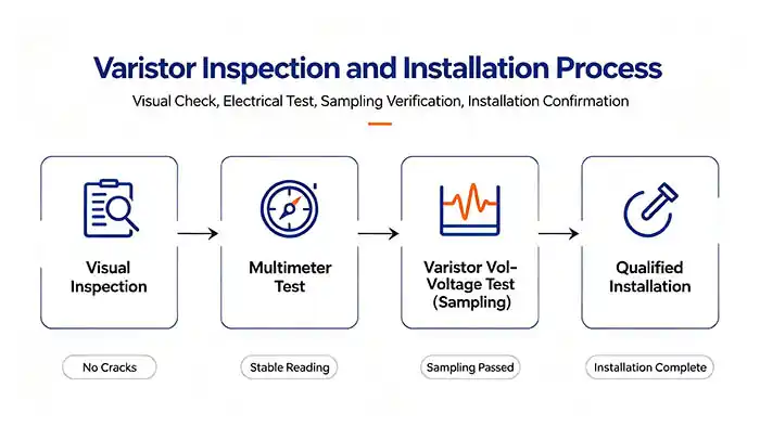
Print this checklist and use it for every shipment of DC SPDs you receive:
| # | Check Item | Pass | Fail |
|---|---|---|---|
| 1 | Packaging intact, no crushing or deformation | ☐ | ☐ |
| 2 | Product model matches purchase order | ☐ | ☐ |
| 3 | Housing has no cracks, burns, melting, or discoloration | ☐ | ☐ |
| 4 | Indicator window shows green | ☐ | ☐ |
| 5 | Terminals are clean, not oxidized, threads intact | ☐ | ☐ |
| 6 | Multimeter shows OL/open circuit between all terminal pairs | ☐ | ☐ |
| 7 | If sampling: varistor voltage within ±10% of spec | ☐ | ☐ |
| 8 | Certificate of conformity and factory test records included | ☐ | ☐ |
Frequently Asked Questions
Q1: Can I test an SPD while it's still in the original packaging?
A: Yes, as long as you can access the terminals without damaging the packaging. The multimeter test requires direct contact with the terminals, so you may need to remove the SPD from its packaging to perform the measurement.
Q2: Why does my multimeter show a slowly increasing resistance when testing an SPD?
A: This is a normal phenomenon. The multimeter's test voltage is charging the internal capacitance of the MOV. The resistance reading will gradually climb as the capacitor charges. Wait for the reading to stabilize before recording it.
Q3: Is it necessary to test every single SPD before installation?
A: For large projects, a sampling approach is typically sufficient—for example, testing 5 units per 100. However, for critical locations such as the main distribution panel feeding expensive equipment, 100% testing is strongly recommended. Always follow your project's quality assurance plan.
Q4: Can a multimeter tell me if an SPD is fully functional?
A: No. A multimeter can only perform a basic go/no-go test—it can tell you if the SPD is shorted (failed) or open (not obviously failed). It cannot verify clamping voltage, response time, energy handling capability, or performance degradation. For comprehensive testing, you need a dedicated SPD tester.
Q5: What's the difference between testing AC SPDs and DC SPDs?
A: AC SPDs must be tested with AC test voltages, while DC SPDs must be tested with DC test voltages. AC/DC SPDs should be tested with DC. Always use the correct test method for your device type.
Summary & Next Steps
Testing a DC surge protection device before installation doesn't require a laboratory—a few minutes of visual inspection and a simple multimeter test can identify most common failure modes. The process is straightforward:
-
Visual inspection – Look for physical damage and verify the indicator shows green
-
Multimeter go/no-go test – Confirm all terminal pairs read as open circuit (OL)
-
Advanced testing – For critical locations or sampling, use a dedicated SPD tester to verify varistor voltage
-
Document everything – Record test results as part of your quality assurance documentation
An SPD that passes these pre-installation checks is much more likely to provide reliable protection once installed. Conversely, catching a faulty SPD before it goes into the combiner box saves you from the far more costly exercise of troubleshooting an unprotected system after a surge event.