 English
 Bahasa Melayu
 Suomen kieli
 عربي
عربي  Português
 Français
 Pусский
 Español
Can a Rapid Shutdown Transmitter Be Used with Multiple Inverters?


In large photovoltaic systems with multiple inverters, a common question arises: can a single rapid shutdown transmitter control all the connected equipment? The short answer is yes—but with conditions. While using one transmitter to initiate shutdown across multiple inverters is often the most cost-effective and cleanest design approach, success depends on compatibility, wiring configuration, signal strength, and code compliance. This article explores when and how a single RSD transmitter can serve multiple inverters, the limitations you need to consider, and best practices for system designers and large-scale plant engineers.
When One Transmitter Can Control Multiple Inverters
Not every system is a candidate for a single-transmitter configuration. The feasibility depends on three key factors: protocol compatibility, control interface type, and communication architecture.
Same Manufacturer and Protocol
If all inverters in the system come from the same brand and use an identical RSD communication protocol, a single transmitter can often drive all of them. In such cases, the transmitter's output can be connected in parallel to the RSD input terminals of every inverter. For example, Solis explicitly states in their installation manuals that when multiple inverters are installed in parallel, "it is ideal to use a single external rapid shutdown transmitter" to prevent cross-talk.
Dry Contact Control
Some rapid shutdown transmitters output a dry contact signal—essentially a relay closure or opening that signals the inverter to initiate shutdown. Any inverter that accepts a dry contact input for RSD can be controlled by the same transmitter, regardless of brand. This makes dry contact one of the most universal methods for multi-inverter control.
Communication Bus
In more sophisticated systems, a single transmitter can act as a master on an RS-485 communication bus, with multiple inverters configured as slaves. The SunSpec RSD communication standard has gained significant industry support, enabling seamless integration and high reliability across systems with many inverters. When using a SunSpec-compliant transmitter, any SunSpec-certified inverter can receive the shutdown signal, providing brand flexibility.
The Limitations – Signal Strength and Distance
Even when compatibility exists, physical and electrical limitations can prevent a single transmitter from serving multiple inverters.
Maximum Drive Capacity
Every transmitter has a maximum current output or a maximum number of slaves it can support. Exceeding this capacity causes signal degradation, potentially leaving some inverters unresponsive to the shutdown command.
Cable Length Constraints
The distance between the transmitter and the farthest inverter matters. Manufacturer specifications vary, but typical maximum round-trip cable lengths range from 100 to 500 meters:
| Transmitter Type | Maximum Cable Length |
|---|---|
| Tigo single-core | 300 m |
| Tigo dual-core | 500 m |
| Hoymiles HT-G20 | 800 m |
| APsmart PLC | Up to 700 m per string |
Signal Wiring Length Between Synced Transmitters
For systems using multiple synchronized transmitters, the signal wiring between transmitters is typically limited to 30 meters.
How to Wire a Single Transmitter to Multiple Inverters
There are three primary wiring methods for connecting one transmitter to multiple inverters.
Parallel Wiring
The most straightforward approach is to connect the transmitter's output terminals simultaneously to each inverter's RSD input terminals. Pay careful attention to polarity and wire gauge. In this configuration, all RSD terminals are wired in parallel—each inverter receives the same signal directly from the transmitter.
Best practice: Use a junction box or terminal block to distribute the signal cleanly, and ensure all connections are secure and properly labeled.
Daisy Chain
Some inverters provide both an RSD input and an RSD output terminal. In a daisy-chain configuration, you connect from the transmitter to Inverter A, then from Inverter A's RSD output to Inverter B's input, and so on. However, not all inverters offer this functionality, so verify the feature before designing the system.
For integrated Tigo transmitters, for instance, daisy-chaining is supported—transmitters can be linked together with two wires, allowing them to synchronize and eliminate cross-talk.
Use a Relay Splitter
If the transmitter's output power is insufficient to drive all connected inverters, install an intermediate relay to amplify the signal. The relay receives the transmitter's low-power signal and uses an external power source to distribute a stronger signal to multiple inverters. This approach is particularly useful in large commercial systems with many inverters or long cable runs.
Code Considerations – NEC 690.12
The National Electrical Code (NEC) does not prohibit using a single transmitter to control multiple inverters. However, several code requirements must be satisfied.
Simultaneous Shutdown Requirement
NEC 690.12 requires that all conductors outside the array boundary drop to 30V or less within 30 seconds during rapid shutdown. With a single transmitter controlling all inverters, the system must be designed so that all arrays shut down simultaneously when the transmitter is activated.
Multiple Initiation Devices Are Permitted
NEC allows up to six grouped initiation devices to operate together to achieve compliance. This means you are not forced to use a single transmitter—you can have up to six separate shutdown switches controlling different sections of a large system, as long as they are properly grouped and labeled.
Single Point of Failure Concern
When one transmitter serves multiple inverters, that transmitter becomes a single point of failure. If the transmitter fails, all connected inverters lose their shutdown capability. For critical systems—especially those serving essential facilities or with high safety requirements—consider redundant transmitter designs or multiple transmitters with synchronized operation.
Brand Mixing and PVRSS Certification
A critical code-adjacent consideration: do not mix RSD brands unless explicitly certified. The PVRSS certification includes the inverter, the PLC transmitter, and the receivers as a matched set. Mixing different brands can violate both the certification and the equipment warranty.
Exception: Midnite Solar receivers can be used with either Tigo or APS transmitters.
When You Might Need Separate Transmitters
Despite the advantages of a single-transmitter design, there are scenarios where multiple transmitters are necessary or preferable.
Inverters Located Far Apart
If inverters are installed at opposite ends of a large building or across multiple buildings, the cable length may exceed the transmitter's maximum communication distance. In such cases, separate transmitters—each located near its respective inverter—are required.
Different Brands with Incompatible Protocols
When inverters come from different manufacturers and do not share a common RSD protocol, a single transmitter cannot control all of them. Each inverter brand may require its own compatible transmitter.
Zoned Shutdown Requirements
Some systems require partitioned control—for example, shutting down only the arrays on one building while keeping another building operational. Separate transmitters enable this flexibility, provided each zone has its own initiation device.
Cross-Talk Prevention
In systems where multiple PLC transmitters must coexist, cross-talk can occur—competing PLC signals from different transmitters can reach the same RSD receivers, causing them to randomly cycle on and off. To mitigate this:
-
Keep PV leads from different inverters separated by at least one foot.
-
Use transmitters with synchronization features, such as Tigo's Pure Signal technology, which allows up to 10 transmitters to link together and coordinate their keep-alive signals.
-
Ensure different transmitter groups' DC conductors are separated by at least 8 inches.
A Practical Example
Scenario: A commercial rooftop installation with three inverters from the same brand (Solis), each located within 50 meters of the central RSD transmitter location.
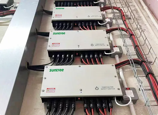
Solution: Use a single external RSD transmitter. Wire the transmitter's dry contact output in parallel to the RSD input terminals of all three inverters. Each inverter independently controls its connected RSD devices. The PV strings are routed through the external rapid shutdown enclosure first, then to each inverter. A single core can handle up to 10 strings, and some transmitters support two cores for up to 20 strings.
Result: Pressing the single initiation button shuts down all three inverters and their connected arrays simultaneously. The system remains code-compliant, avoids cross-talk, and minimizes equipment costs.
Frequently Asked Questions (FAQ)
Q1: Will using one transmitter for multiple inverters create a single point of failure?
A: Yes. If the transmitter fails, none of the connected inverters can initiate rapid shutdown. For safety-critical systems, consider redundant transmitter designs or using multiple synchronized transmitters as permitted by NEC.
Q2: Can I mix string-level and panel-level RSDs with one transmitter?
A: Generally, no. The transmitter must be matched to the specific RSD devices it controls. Mixing different types or brands of RSD receivers can lead to communication protocol conflicts and may void the PVRSS certification and equipment warranties.
Q3: How do I test that all inverters respond to the same transmitter?
A: Press the RSD initiation button, then check each inverter's display or indicator LED. All should show "RSD active," "Shutdown," or a similar status message. Additionally, measure the DC voltage at the array—it should drop to the safe level within 30 seconds.
Q4: What if my inverters have built-in transmitters?
A: If you plan to use an external transmitter, the internal transmitters must be disabled to prevent cross-talk between competing PLC signals. Consult the inverter manual for the specific procedure.
Q5: Can I use one transmitter with inverters from different brands?
A: Only if:
-
The transmitter outputs a dry contact signal and all inverters accept dry contact RSD inputs.
-
All inverters and the transmitter are SunSpec-certified and use the same SunSpec RSD communication protocol.
Otherwise, mixing brands typically violates PVRSS certification.
Summary & Next Steps
A single rapid shutdown transmitter can control multiple inverters—provided that:
-
Protocol compatibility exists
-
Distance limitations are respected
-
Output power is sufficient for all connected inverters
-
NEC 690.12 requirements are met
-
Brand mixing is avoided unless explicitly certified
The single-transmitter approach offers significant benefits: reduced equipment costs, simplified wiring, and elimination of cross-talk risks. However, system designers must carefully evaluate the single point of failure risk and consider redundancy for critical installations.
Consult SUNTREE engineers to design the optimal RSD control solution for your multi-inverter system. Our team can help you navigate compatibility, wiring, and code compliance to ensure a safe, reliable, and cost-effective rapid shutdown implementation.