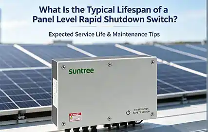
How to reduce DC Isolating Switch failure frequency?
To fundamentally reduce the failure rate of DC isolating switch, you need a three-pronged strategy: selecting arc-resistant, certified components, such as Suntree's specialized models;

• UV and ozone resistant, hydrolysis resistant.
• High temperature resistance, service life of more than 25 years.
• Good flexibility, easy installation and laying.
• Halogen-free and low-smoke material, in line with environmental protection requirements.
• Compatible with all common connectors.

| TECHNICAL INOICATORS | |
| Nominal voltage | U0/U 0.6/1KV(AC)1800DC(non-load) |
| Test voltage | AC6.5KV/5min(20°±0.5) or DC15KV/5min(20°C±0.5) without breakdown |
| Ambient temperature | -40℃~+90℃ |
| Conductor maximum temperature | 120℃ |
| Maximum short circuit temperature | ≤250℃/5s |
| Expected service life | 25 years |
| Bending radius | ≥4D |
| STRUCTURE | |
| conductor | Tinned copper flexible conductor of Class 5 in 2Pfg1169 |
| lnsulation | LSZH electron-beam cross-linked Polyolefin(125℃) |
| sheath | LSZH electron-beam cross-linked Polyolefin(125℃) |
| color | red or black |
| CHARACTERISTICS COMPLIANCE | |
| Fire-resistance | EN 60332-1-2 |
| Acid and alkali solution | EN 60811-2-1 |
| Halogen determination | EN 50267/EN 60684 |
| Weather resistance/UV resistance | HD 605/A1 |
| Compliance certification | ROHS TUV |
| Executive standard | 2 Pfg 1169/08.2007 |
Structural dimensions and parameters
| Model | Specification (mm²) |
Insulation Nominal Thickness (mm) |
Sheath Nominal Thickness (mm) |
Approximate outer diameter (mm) |
Maximum DC resistance of conductor at 20℃ (Ω/km) |
Minimum insulation resistance at 90℃ (mΩ/km) |
| PV1-F | 2×2.5 | ≥0.5 | ≥0.5 | 5.2×10.9 | 8.21 | 0.69 |
| PV1-F | 2×4.0 | ≥0.5 | ≥0.5 | 5.9×12.2 | 5.09 | 0.58 |
| PV1-F | 2×4.0 | ≥0.5 | ≥0.5 | 5.5×11.4 | 5.09 | 0.58 |
| PV1-F | 2×4.0 | ≥0.5 | ≥0.5 | 4.85×10 | 5.09 | 0.58 |
| PV1-F | 2×6.0 | ≥0.5 | ≥0.5 | 6.2×112.9 | 3.39 | 0.50 |
| PV1-F | 2×6.0 | ≥0.5 | ≥0.5 | 5.35×11.2 | 3.39 | 0.50 |
| PV1-F | 2×10 | ≥0.5 | ≥0.5 | 7.3×15.1 | 1.95 | 0.42 |
Reference table for quick selection of carrying capacity
| Cross-sectional area | Recommended valueof ampacity (A) | Download traffic conversion factor for different ambient temperatures | |
| Copper conductor | Laying in the air | Ambient temperature ℃ | Conversion factor |
| 2×2.5 | 33 | 60 | 0.71 |
| 2×4 | 44 | 70 | 0.58 |
| 2×6 | 57 | 80 | 0.41 |
| 2×10 | 79 | ||
| 2×16 | 107 | ||
Note: Ambient temperature is 30°C; conductor maximum temperature is 90℃
GET A QUOTE